312 Programming examples - Helicopter models
»Control adjust« (page 112 … 119)
0%
I13 +100%
I14
I15
Tl16
Typ
+100%
– travel + –time+
0%
+100%
+100%
0.0 0.0
0%
+100%
+100%
0.0 0.0
0%
+100%
+100%
0.0 0.0
GL
GL
GL
fr
fr
Lv1
---
---
---
offset
GL
Normal
0.0 0.0
fr ---
SET
… where input "Tl16" is assigned and all other inputs
are "fr(ee)" by default.
This "Tl16" input serves as the throttle limiter. Its
effect is exclusively on output "6", where the throttle
servo is connected. The throttle limiter is assigned by
default to the right-side proportional rotary control.
Once again, as a reminder:
With the user of the "throttle limiter" function, you •
do not have to program a fl ight phase "throttle pre-
selection".
The throttle limiter does not control the throttle •
servo; it only limits the travel of the throttle servo
in the full throttle direction according to its position.
The throttle servo is generally controlled from
the pitch joystick via »Helicopter mixer« menu
setting/s for throttle curve/s, which is why input
6 must absolutely remain "free". Refer to pages
180 through 182 in this manual about this.
The C1 trimming also affects only the throttle servo •
for the helicopter. At this point there is no need to
go into the particulars of this trimming once again.
Please read more about this on page 58. (Thanks
to the digital trimming, trim can be automatically
saved values with a model changeover as well as
with a change of the fl ight phase).
A detailed description of the idle run base setup •
model and the adjustment of idle and throttle limit
can be found beginning on page 117.
Then switch to the "travel" column with the
selection key of the left or right touch pad and
increase the now inversely highlighted value from
+100 % to +125 % with a fully opened throttle limiter
with a brief tap on the center
SET key of the right
touch pad:
0%
I13 +100%
I14
I15
Tl16
Typ
+100%
– travel + –time+
0%
+100%
+100%
0.0 0.0
0%
+100%
+100%
0.0 0.0
0%
+100%
0.0 0.0
GL
GL
GL
fr
fr
Lv1
---
---
---
offset
GL
Normal
0.0 0.0
fr ---
+125%
SET
In doing so, it is assured that the throttle limiter
releases the entire throttle travel with the pitch
joystick later during fl ight.
Adjustment notice for electric helicopters:
Since electric drive systems have no need for an
idle setting, the basic confi guration of settings for
an electrically-powered helicopter merely involves
making sure that the control range of the throttle
limiter is both higher and lower than the adjustment
range of the speed controller (usually -100 % to
+100 %) by a safe margin. If necessary, therefore,
the adjustment of the "travel" setting of the throttle
limiter described above must be modifi ed accordingly,
for example, to symmetric 110 %. The further
adjustment, however, can take place analogously to
the combustion helicopter described here.
With this process, you have not carried out the basic
settings for the transmitter as they are needed again
later for further model programming.
The actual helicopter-specifi c settings take place
primarily in the menu …
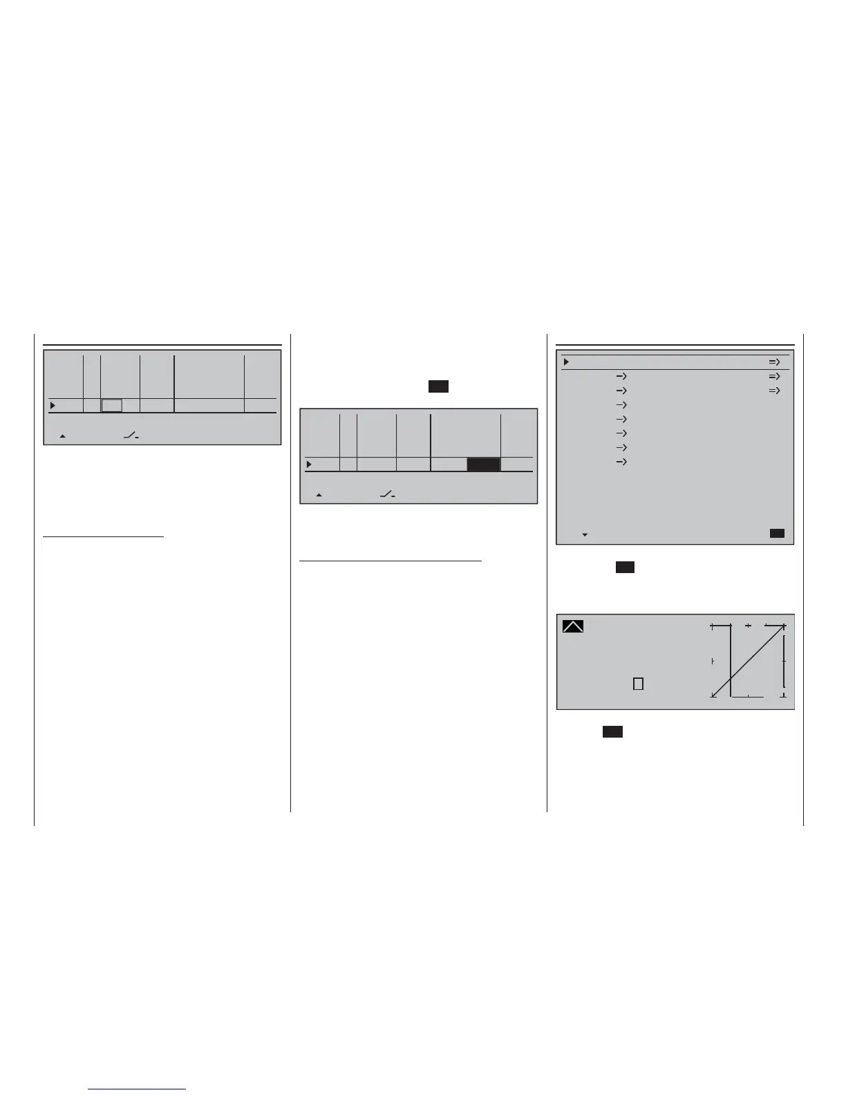
» Helicopter mixer« (page 176 … 191)
Channel 1
Channel 1
Pitch
Throttle
Tail rot.
Tail rot.
0%
Roll
0%
Throttle
Roll
Throttle
Tail rot.
Nick
Nick
Throttle
Tail rot.
Swashplate rotation
Swashplate limiter
0%
0%
0%
0°
off
Gyro suppression
0%
Gyro offset
0%
Normal
The "Pitch" function appears right in the fi rst line. A tap
on the center SET key of the right touch pad will cause
a switch to the corresponding sub-menu. The graphic
representation of the pitch curve appears here; it is
initially only defi ned by the points "L" and "H":
Pitch
Curve
off Point
Output
Input –50%
–50%
?
+
–
100
O U T P U T
0%
Normal
Now place point "1" in the center with a brief tap on
the center SET key of the right touch pad:

 Loading...


