11
Position the motor so that the distance between nose bulkhead and propeller driver is 120 mm. In this
position mark the location of the screw holes on the motor mount arms, working through the motor
mounting lugs.
Drill 2 mm Ø pilot-holes in the mount arms to accept the 2.4 mm Ø pan-head self-tapping screws. Drill
a hole for the throttle pushrod (see below), and fit the plastic sleeve (supplied) in it, running to the
throttle servo. Connect the throttle pushrod to the carburettor lever, and slip it into the plastic sleeve.
The motor can now be fixed to the mount using the screws mentioned above.
Attach the silencer to the motor using the appropriate fixings.
Assembling and installing the fueltank
Cut a piece of silicone fuel tubing and push it onto the fueltank clunk weight. Push the free end of the
fuel tubing onto one of the tubes in the fueltank stopper, and check that the clunk will be able to move
freely inside the tank without binding or jamming when the stopper is in place. Bend the tubes to the
shape shown in the illustration, then push the tank stopper over the neck of the fueltank. Check that
one pipe points down (filler line) and one up (vent line; this is connected to the silencer pressure nipple
later). Cut three pieces of silicone fuel tubing and push them onto the tubes where they exit the
fueltank. Mark the fuel lines using a felt-tip pen or coloured tape to indicate which is the fuel feed, the
overflow and the filler. Push the stopper into the tank and tighten the cross-point clamping screw.
Ensure that the screw is tight enough to seal the fueltank completely.
Fit the fueltank through the wing saddle and into the tank compartment in the fuselage. Pack foam
round the tank, and ensure that it cannot shift in flight.
Connecting the fuel lines
Connect the silicone fuel line attached to the clunk weight to the carburettor nipple. Connect the
overflow line to the pressure nipple on the silencer.
To fill the fueltank the filler line should be routed through a hole and out of the cowl; this line should be
sealed after re-fuelling and before starting the motor (sealing nipple: Order No. 140).
Attaching the cowl
Glue the screw-blocks to the annular former on the nose bulkhead, spaced out as shown in the
pictures. Fit the cowl over the annular former and mark the position of the holes in the moulding. Drill 3
mm Ø holes at the marked points. Fit the cowl over the annular former again and mark the position of
the holes on the screw-blocks. Drill 2 mm Ø pilot-holes, and fix the cowl to the fuselage using the
screws supplied. Fit the propeller and spinner on the motor. It is important to check regularly that the
propeller is firmly seated.
Dummy pilot and canopy
The instrument panel and dummy pilot can now be installed. Glue the pilot in the cockpit. Drill four
holes for the canopy and fix it to the top of the fuselage using the screws supplied.
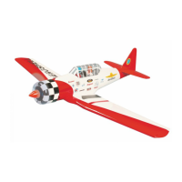
Assembling the North American Harvard AT-6
Before assembling the model the plywood doublers must be glued to the underside of the wing to
spread the load of the retaining screws. Run the aileron servo and retract servo leads through the
circular opening, and pack a little foam plastic round them to prevent them chafing.
To make it easier to connect the aileron servos to the receiver we recommend connecting a
suppressor filter, Order No. 1040, to each of the appropriate receiver sockets (2 and 5). Pack the
receiver battery in foam and stow it in the fuselage; make sure it cannot possibly shift in flight. Connect
the aileron servos to the extension leads, then fix the wing to the fuselage using the two retaining
screws supplied.
Balancing the North American Harvard AT 6
Support the assembled model under both wing roots, where the retract units are fitted, at a point about
90 mm aft of the wing leading edge. If the CG position is correct the model will hang level, with the
nose inclined slightly down. Tip: as this is a low-wing model, it is better to hold it inverted (upside-
down) for balancing.
If necessary, adjust the position of the receiver battery to correct the CG position. If this is not
sufficient, glue lead ballast (Order No. 541) to the nose or tail to obtain the correct balance.
All the control surfaces must be exactly at centre when the transmitter sticks and trims are in the
neutral position; check this before the first flight.
 Loading...