31 32
◎ MISC PAGE (Addition function)
Tap the MISC icon to program the MISC
setup on the main page
Additional functions on CH1 or CH2 can also
be used.
This is the MISC setup page.
Tap the 3 icons to access each mode. Tap the ESC button to
return to the previous page.
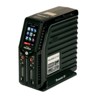
Tap the MISC icon on the main page to access the MISC mode and to program the
Servo, Brushless/Brushed power motor, and Warmer functions.
- Used to test the Servo and Brushless Motor.
- Used to test and condition the Brushed Motor.
- Used to warm up the batteries and tires.
- Used for the
speed controller
setup and settings.
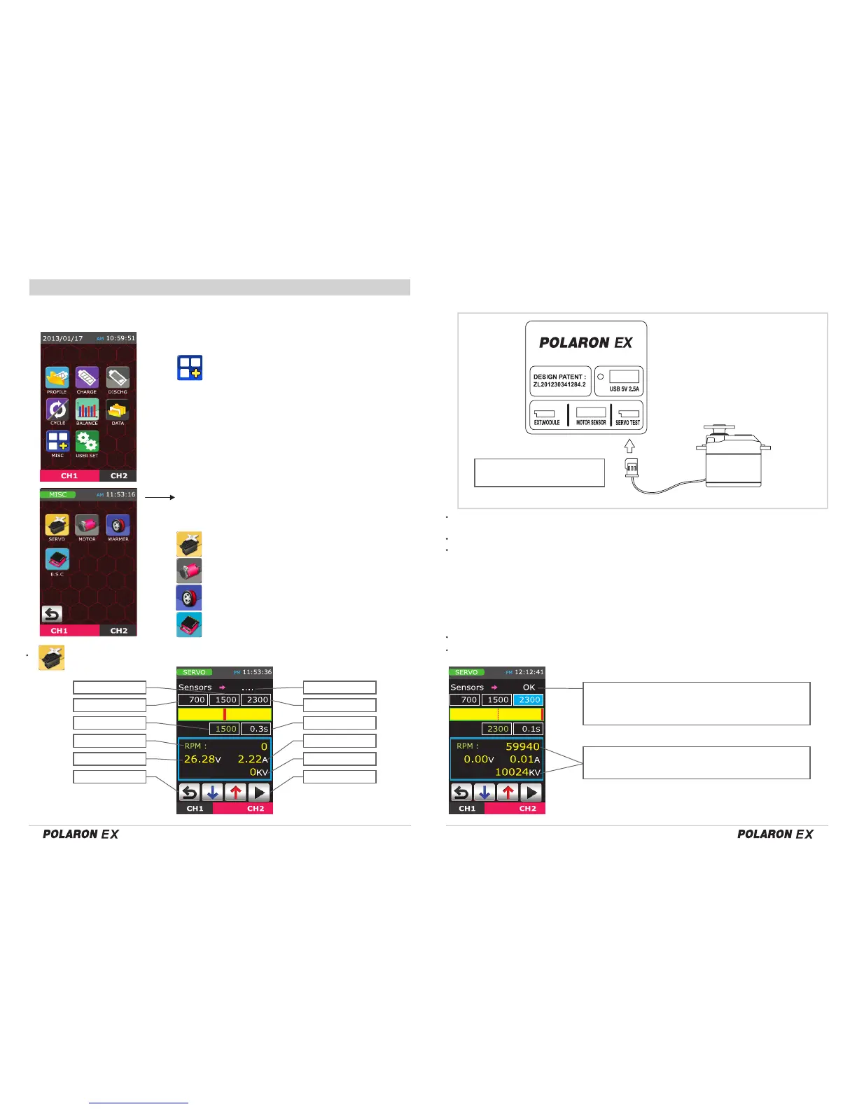
Servo and Brushless motor testing setup
Check the servo connector
polarity S,+,-
1) Servo test division (Screen top)
- Connect the Servo to the connecter on the right side of the charger
(see picture, below).
2) Motor test division (Screen Top and bottom)
- Motor sensor connector and servo test connector are both used.
Min, Mid, Max signal
Auto loop time
Output signal
The 3 sensors at the top indicate if the motor is OK or not.
RPM and Kv are shown at the bottom.
:
Tap the relevant buttons. The servo is operated in accordance with the preset
signal. The parameters of each article can be changed by tapping the DEC/INC buttons.
: After entering the Auto loop time (0.1 - 5.0sec),
tap the Enter button.
High power servos may not function well using only short operatinng times, as
these servos often require a high peak current demand. For these servos,
extend the operating time to accomodate the increased peak current
requirements.
Continuously rotate the motor shaft for approximately 5 seconds.
The charger will then indicate if the sensor is OK or not.
The motor should be connected to the motor sensor connector.
An (optional) splitter is required to check the motor RPM
and Kv. (Please refer to the picture on the next page.)
: Displays the current signal output parameters.
Mid signal Sensor check
Min signal Max signal
Output Signal Auto loop time
Motor RPM Output current
Output voltage Kv data
Stop Start
USER NAME

 Loading...