GRAUPNER GmbH & Co. KG D-73230 KIRCHHEIM/TECK GERMANY
Changes reserved! No liability for printing errors! 3/2012
5
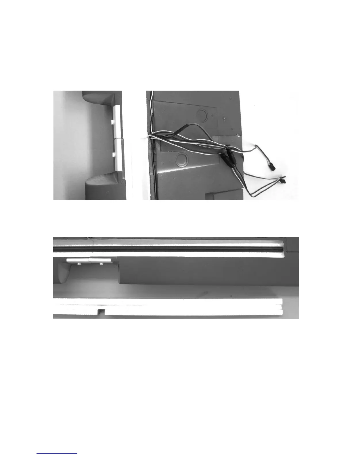
The figure shows the assembled right wheel spat, the left wheel spat is assembled in
the same manner. Now fasten the landing gear bow to the fuselage with the M4 x
25 mm long countersunk head screws. With this step, the fuselage assembly is
already complete.
The wing
Make a "dry run" assembly (i.e. without glue) of both wing halves first. When gluing
the wing halves, be sure everything is properly aligned then press them together
tightly.
Glue in the CFRP wing spar then finish by gluing on the spar cover. Check the
stability of the spar's glue bond with a stress test.
RC installation
Position the HoTT receiver between the two seats in the model's cabin to ensure its
fit there. Later on it will be fixed in place there with Velcro ribbon. For the time being,
just lay the receiver loosely on the fuselage then plug the servos into the receiver so
the wing's flap functions can be adjusted and tested. We recommend the following
receiver socket layout: the speed controller in socket 1, the left aileron servo in
socket 2, elevator servo in socket 3, rudder servo in socket 4, right aileron servo in
socket 5 and the V-cable for the landing flaps in socket 6. Attention: When the G3.5