EN - 32
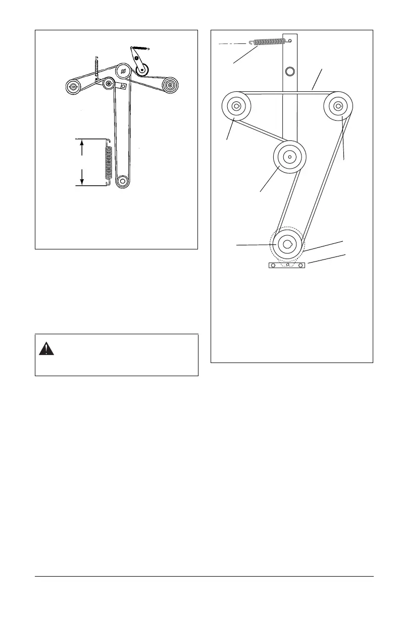
Replacing the Hydro Pump Belt
(Figure 24)
1. Properly stop and park unit (See
OPERATION on page 16).
2. Remove the PTO belt from the mower
clutch sheave (See Replacing Mower
Belts on page 30).
3. Slowly release the tension on the hydro
pump belt idler until all the tension is
removed from the springs.
4. Remove old hydro pump belt from right
hand hydrostat sheave first.
5. Install new hydro pump belt by
positioning belt on sheaves. Put belt
onto right hand hydrostat sheave last.
6. Replace long mower belt on mower
clutch sheave. See Replacing Mower
Belts on page 30.
MOWER DECKS
Anti-scalp Roller Adjustment
The anti-scalp rollers are set at the factory for
typical mowing height, but can be adjusted for
high or low cutting conditions (Figure 25).
Anti-Scalp rollers are intended to prevent
lawn scalping, not to control cutting height.
For a very high cutting height, set the anti-
scalp rollers in the lowest position on the
bracket.
For a very low cutting height, set the anti-
scalp rollers in the highest position on the
bracket.
NOTE: There are four anti-scalp rollers on
the outside of the mower deck and four anti-
scalp rollers on the inside of the mower deck.
Make sure all anti-scalp rollers are set at the
same height.
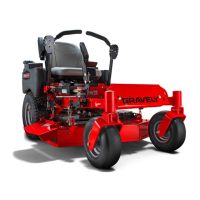
CAUTION: Use care when releasing
idler spring tension. Keep body parts
well away from idlers when
performing this operation.
Figure 23
The PTO idler spring length range is
12.25 – 12.5" (31 – 31.8 cm) measured at
a 3.5" (8.9 cm) cutting height. Adjust as
necessary.
Measure
PTO idler
spring
length
here.
60" PTO Idler Spring Length
Figure 24
1. Hydro Belt
2. Spring
3. Idler
4. Engine Sheave
5. Right Hand Hydrostat
6. Left Hand Hydrostat
7. Clutch
8. Clutch Anchor
6
1
5
2
7
8
4
3