EN - 33
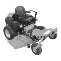
ALIGNING THE STEERING
LEVERS
Additional Steering Lever
Adjustments
(Figure 22)
1. Shut off engine. Remove the ignition
key.
2. Place seat in the service position (See
Service Position on page 26).
3. Check that upper and lower steering
levers are aligned parallel to each other.
There should be a maximum of 1/8” (3.2
mm) difference between the top and the
bottom.
• If upper and lower steering arms are
not parallel, loosen mounting
hardware, reposition top lever and
tighten hardware.
4. Disconnect the steering linkages from
the transaxle.
5. Engage parking brake.
6. Turn the eccentric spacer until the
steering levers align.
7. Loosen the jam nut at the bottom of the
tie rod and then turn the ball joint to align
it with the transaxle control arm, and
then connect the linkage to the control
arm.
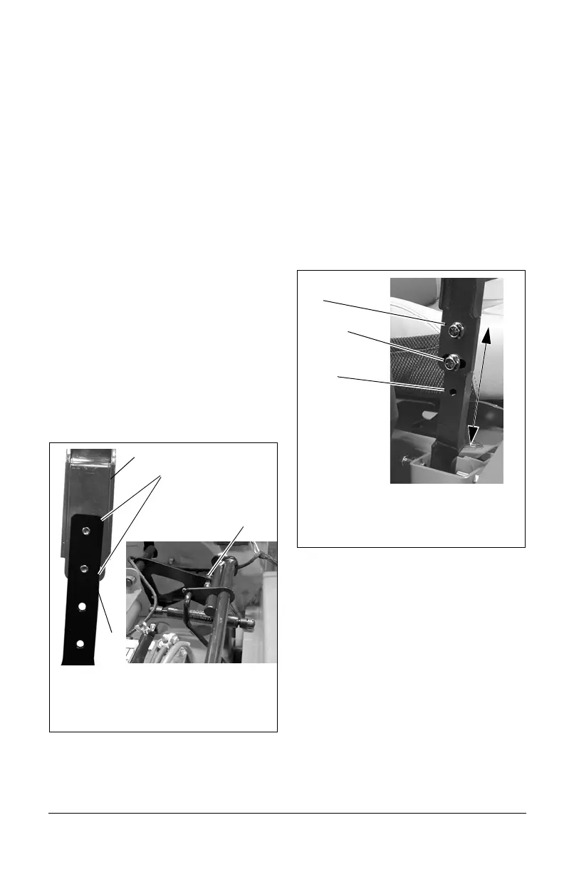
Adjust Lever Height
(Figure 23)
1. Shut off engine. Remove the ignition
key.
2. Remove pivot bolt and angle adjustment
bolt from steering lever assembly and
remove steering lever assembly.
3. Position the steering lever assembly to
use the upper and middle holes for
highest steering lever position.
4. Position the steering lever assembly to
used the middle and lower holes for the
lowest steering lever position.
IMPORTANT: Ensure that both levers are
aligned and do not make contact with each
other.
Adjust Upper Lever Angle
(Figure 24)
1. Shut off engine. Remove the ignition
key.
2. Place steering levers in outward
position.
3. Loosen lock nut and rotate steering level
height stop until desired height is
achieved:
• Turn stop counter-clockwise to
increase lever angle.
• Turn clockwise to decrease upper
lever angle.
4. Move levers into operating position to
check lever height and orientation.
Figure 22
1. Upper Steering Lever
2. Lower Steering Lever
3. Eccentric Spacer
Align upper and lower
steering levers so
that top dimension is
within 1/8" (3.2 mm)
of bottom.
1
2
3
Figure 23
1. Pivot Bolt (Upper Hole)
2. Angle Adjustment Bolt (Middle Hole)
3. Lower Hole
1
2
3