6
FUEL SYSTEM
CARBURETOR
Fi
ure 2
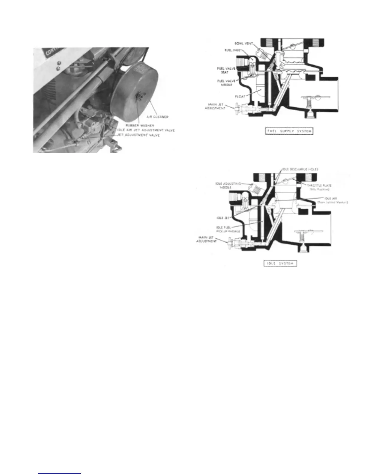
Figure 3
Figure 4
A. Adjustment
1. Screw the main jet adjustment needle (a brass T-needle) in
until it is snug. Do not force or screw it tightly.
2. Back off the main jet adjustment needle 1'z turns.
3. Start the engine and open the throttle halfway.
After the engine warms up, begin screwing the needle,
slowly. As soon as the engine begins to slow down, stop and
back the needle off until the engine picks up speed.
4. Screw the idle air jet adjustment needle all the way in; then
back off one turn. Start the engine and allow it to idle. Screw
the needle in until the engine begins to run rough. Then back
the needle off until engine runs smooth.
FUEL SUPPLY SYSTEM
(See Figure 3)
The fuel supply system is made up of the threaded fuel
inlet, the fuel valve seat, fuel valve needle, float and fuel bowl.
The fuel supply line is connected to the threaded inlet. The
fuel travels through the fuel valve seat and passes around the
fuel valve and into the fuel bowl. The level of the fuel in the
fuel chamber is regulated by the float through it control of the
fuel valve. The fuel valve does not open and close alternately
but assumes an opening, regulated by the float, sufficient to
maintain a proper level in the fuel chamber equal to the
demand of the engine according to its speed and load.
The inside bowl vent as illustrated by the passage
originating in the air intake and continuing through to the fuel
bowl, is a method of venting the fuel bowl to maintain proper
air fuel mixtures even though the air cleaner may become
restricted. This balancing is frequently referred to as an "inside
bowl vent".
IDLE SYSTEM
(See Figure 4)
The idle system consists of two idle discharge holes, idle
air passage, idle adjusting needle, idle jet and fuel
pick-up passage.
The fuel for idle is supplied through the main jet to a well
directly below the main discharge jet. The pick-up passage is
connected to this well by a restricted drilling at the bottom of
this passage. The fuel travels
through this channel to the idle jet calibration. The air for the
idle mixture originates back of (or from behind) the main
venturi. The position of the idle adjusting needle (normally one
turn from its seat) in this passage controls the suction of the
idle jet and thereby idle mixture. Turning the needle in closer
to its scat results in a greater suction with a smaller amount of
air and therefore a richer mixture. Turning the needle out away
from its scat increases the amount of air and reduces the
suction, and a leaner mixture is delivered. The fuel is atomized
and mixed with the air in the passage leading to the discharge
holes and enters the air stream at this point.
HIGH SPEED SYSTEM
(See Figure 5)
The high speed system controls the fuel mixture at part
throttle speeds and a wide open throttle. This system consists
of a venturi, controlling the maximum volume of air admitted
into the engine; the main jet, which regulates the flow of fuel
from the float chamber to the main discharge jet; the well vent,
which maintains uniform mixture ratio under changing suction
and engine speeds; and a main discharge jet, which delivers
the fuel into the air stream.
The main jet controls the fuel delivery during the