8
(c) Install main jet and fibre washer.
(d) Install the drain plug (hex) in threaded passage bottom of
fuel bowl
(e) Install main jet adjustment seat lightly and back out 1 1/2
turns.
THROTTLE BODY
(a) Install idle adjusting needle and friction spring in
threaded passage on side of throttle body. Seat lightly
with screwdriver and back out one full turn.
(h) Install idle jet.
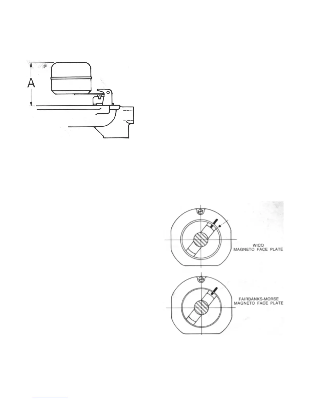
Figure 7
ELECTRICAL SYSTEM
Spark Plug -Champion H-8 Gap - .025 inch
Timing
1. Remove cylinder head and gasket.
2. Loosen magneto coupling bolt until coupling will slip on the
camshaft extension.
3. Bring the piston to top dead center on compression stroke
(both valves closed).
4. Back piston down cylinder approximately one inch by turning
starter pulley counterclockwise.
5. Measure accurately 3/8 inch from top of cylinder and bring
piston up to this point.
6. Align the timing marks (straight marks) on magneto.
7. Reassemble the magneto coupling using .015 feeler gauge
between the fibre block and the coupling flange before
tightening bolt so as not to clamp the impulse.
8. Reinstall head and gaskets torquing to 20 ft. lbs.
LUBRICATION
The only lubricating point in the magneto is the cam wiper
felt. This felt, which lubricates the breaker arm at point of
contact with the cam, should be lubricated with 2-3 drops oil
whenever it is necessary to replace the breaker contacts.
IMPORTANT
Incorrectly adjusted spark plug gaps cause magneto failure
more frequently than any other condition. Spark plugs
should be inspected at frequent intervals, the size of the gap
should be carefully checked and adjusted and the plugs
thoroughly cleaned. All oil, grease, and dirt should
frequently be wiped off the magneto, lead wires, and spark
plug insulators.
(c) Install fuel valve seat and fibre washer.
(d) Install fuel valve needle in seat followed by float and float
axle.
SEE FIGURE 7. The "A" dimension should be 1 5/32
inch plus or minus 3/64 inch.
(e) Float Level. Check position of float assembly for correct
measurement to obtain proper float level using depth
gauge.
NOTE: Do not bend, twist or apply pressure on the float
bodies.
1 (1) With bowl cover assembly in an inverted position,
viewed from free end of float, the float must be
centered and at right angles to the machined surfaces.
The float setting is measured from the machined
surfaces (no gasket) of cover to top side of the float
bodies at highest point.
(2) Bending Float Lever. To increase or decrease distance
between float body and machined surface use
long-nosed pliers and bend lever close to float body.
NOTE: Replace with new float if position is off more than
1/16 inch.
ASSEMBLE CARBURETOR BODIES
(a) Assemble the two completed bodies and four screws and
tighten screws evenly and firmly.
(b) Hold the throttle lever in a closed position and turn the
throttle stop screw in until it just contacts the stop on body,
then turn screw in 1'/z additional turns.
Fi
ure 8
Keeping these parts clean and the spark plugs properly adjusted
will improve the engine performance and at the same time will
prolong the life of the magneto.

 Loading...