Do you have a question about the GREAT PLAINS 606NT and is the answer not in the manual?
Secure the drill for transport to prevent damage and injury.
Connect the drill to the tractor, including hydraulic hose attachment and re-phasing.
Adjust the toolbar height using a depth stop for field operation.
Ensure the drill frame is parallel to the ground by adjusting the hitch turnbuckle.
Set coulter depth by adjusting the gauge wheel spindle position.
Fine-tune coulter depth by adjusting the spring bar length.
Set the initial spring force for coulters, advising against over-tightening.
Correct positioning of 'W' clips for opener spring rods.
Control seeding depth by adjusting the press wheel height with the 'T' handle.
Re-adjust drive idlers after initial use and each season for chain tension.
Calibrate seed cups to ensure accurate seed rate settings.
Select the correct feed cup handle position for different seed types.
Choose the appropriate gearbox drive type ratio for various seeds and rates.
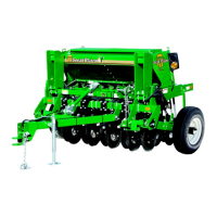
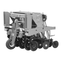
This document serves as a comprehensive field adjustment guide for Great Plains Six Foot No-Till Drills, specifically models 606NT and 3P606NT. It outlines essential procedures for proper servicing and adjustment, crucial for ensuring the longevity and optimal performance of the equipment while preventing costly maintenance and repairs. The guide emphasizes a systematic approach to inspection and adjustment, providing detailed instructions to assist operators in maintaining their drills effectively.
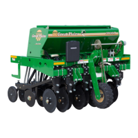
The Great Plains Six Foot No-Till Drills are designed for efficient planting in no-till farming environments, minimizing soil disturbance while accurately placing seeds. These drills are equipped with various adjustable components that allow operators to fine-tune the machine for different field conditions, seed types, and desired planting depths. The core function revolves around precise seed delivery and consistent soil penetration, ensuring optimal germination and crop establishment. Key functional areas include transport, hitching, tool bar height adjustment, leveling, coulter depth control, opener down pressure, seed cup adjustment, and drive type selection. Each of these functions is critical for the drill to perform its primary task of planting seeds effectively in diverse agricultural settings.
The drills incorporate several features designed to enhance usability and adaptability in the field:
Transporting the Drill: For safe transportation, the drill is equipped with transport locks that must always be engaged. This prevents damage to the drill and mitigates personal injury risks in case of hydraulic failure. The procedure involves fully raising the drill, placing the transport lock onto the cylinder rod, and securing it with a pin and clip. Additionally, the lockout hub must be disengaged before transport. This safety feature is paramount for moving the heavy machinery between fields or storage locations.
Hitching 606NT to the Tractor: Hitching involves a multi-step process to ensure proper connection and hydraulic function. First, with the drill lowered and the tongue jack in the parking position, the tongue is leveled. The tractor is then backed up to the drill hitch, and the hitch height is adjusted using the implement jack to match the tractor’s draw bar. After connecting the drill and attaching hydraulic hoses, the drill is raised to its maximum height and held for 30 seconds to re-phase the cylinders. This re-phasing procedure removes air from the hydraulic system, allowing the drill to raise and lower evenly. Repeating this procedure several times a day ensures consistent lifting performance.
Setting Tool Bar Height 606NT: The tool bar height, critical for consistent planting depth, is controlled by a depth stop on the left lift cylinder. The suggested initial operating height is 24 3/4 inches (62.9 cm) from the base of the opener tool bar to the ground when lowered in the field. To adjust, the drill is lowered to the desired height, and pulled forward to engage the openers. The nut and bolt securing the stop weldment are loosened, and the weldment is slid up the rod until it contacts the valve actuator, then an additional 1/8 inch. After tightening, the drill is raised and lowered several times to confirm the depth stop is working correctly, and the desired depth is achieved.
Leveling The Drill 606NT: Proper leveling ensures uniform planting depth across the entire width of the drill. The drill must be lowered until weight is off the hitch turnbuckle before adjustment. The jam nuts on the hitch turnbuckle are loosened, and the turnbuckle is shortened or lengthened until the top of the drill frame is parallel to the ground. Operators are cautioned not to extend the clevises beyond the turnbuckle. Once level, the jam nuts are re-tightened.
Adjusting 3-Point Height 3P606NT: For 3-point hitch models, coulter depth is adjusted by raising or lowering the gauge wheel spindle. Raising the spindle provides deeper coulter depth, while lowering it results in shallower depth. The guide explicitly states not to lower coulters to aid in penetrating hard soil; instead, increasing coulter down-force or adding optional weight is recommended. A table provides coulter depths corresponding to different axle hole positions (from top) for new coulter blades. To adjust, the drill is raised, chain idlers are loosened, wheel bolts are removed, the spindle is moved to the desired hole, wheel bolts are re-installed, and chain idlers are re-engaged.
Individual Coulter Height Adjustment: Individual coulter depth can be fine-tuned by adjusting the spring bar. The process involves determining the desired depth, raising the drill until coulters just touch the ground (with press wheels supporting some weight), and measuring the current spring bar length. The factory setting is approximately 12 1/2 inches (31.8 mm). Clamp bolts are loosened, and a mallet is used to adjust the bar height. Once the desired height is achieved, the clamp bolts are re-tightened.
Coulter Down-Force Adjustment: Coulter springs are factory-preset to provide an initial operation force of 400+ lbs, suitable for most field conditions. Re-setting the coulter spring shorter than 9 3/4 inches can lead to premature failure of parts, highlighting the importance of adhering to recommended settings.
Opener Down Pressure: The "W" clips on the opener spring rods control down pressure. They should typically be in the lowest hole for all conditions. However, if penetration is inadequate, especially behind wheel tracks, the "W" clips can be raised one hole to increase down pressure.
T-Handle Adjustment: The depth of each opener is controlled by the press wheel height, adjusted via a T-handle. Moving the T-handle towards the front of the opener shallows the depth, while moving it towards the rear increases the depth. A good starting point is to place the T-handle in the center position.
Seed Cup Adjustment: Regular inspection of seed cups is crucial to ensure they are clean and free of obstructions. The seed rate handle should move freely without excessive play. To check accuracy, the seed adjustment handle's wing nut is loosened, and the handle is slid to 100. A seed calibration tool (817-459C) is inserted into the seed cup, and the seed adjustment handle is slid until the feed wheel presses tightly against the block. The brass gauge should read 50%. If not, the two screws holding the gauge are loosened, the brass plate is adjusted to read 50%, and the screws are re-tightened.
Feed Cup Adjustment (Four-Position Handle): Each feed cup has a four-position adjustment handle for different seed types and conditions:
Select Drive Type: The gearbox offers various drive speeds for different seed types and rates. It features a linear shaft pattern design with constant mesh gearing, fully sealed to prevent dirt ingress. No lubrication is required unless service is needed. To set the gearbox, the selector handle is moved until the desired drive type appears in the window on the handle. The guide provides ratios for different drive types: Type 2 is 2.06 times faster than 1, Type 3 is 3.08 times faster than 1, and Type 4 is 5.03 times faster than 1.
The guide emphasizes proactive maintenance to extend the drill's lifespan and prevent operational issues:
General Information: Proper servicing and adjustment are highlighted as key to the long life of all farm equipment. Regular, systematic inspection helps avoid costly maintenance, downtime, and repairs. The provided information assists with recommended servicing and adjustments.
Drive Idler Adjustment: Two idler sprockets inside the left-hand gauge wheel arm require re-adjustment after the first 100 acres of use, and then at the beginning of each subsequent season. The process involves loosening the jam nut, moving the front idler sprocket on top of the chain, and tightening the chain by screwing in the adjustment stud. The jam nut is then re-tightened to maintain idler position. A crucial warning advises against over-tightening the stud, as insufficient slack can lead to excessive wear and premature chain failure.
Seed Cup Cleanliness: Operators are instructed to regularly check all seed cups to ensure they are clean and free of obstructions. This prevents blockages that could affect seeding accuracy and consistency.
Storage Recommendations: For long-term storage after the drilling season, it is recommended to place the feed cup adjustment handle in the bottom position (clean out) to prevent damage from mice, which might otherwise nest in or chew on components.
Gearbox Design: The gearbox is designed for minimal maintenance, being fully sealed to keep dirt out and requiring no lubrication unless specific service is needed. This reduces the frequency and complexity of routine maintenance tasks for this critical component.
By following these detailed instructions and recommendations, operators can ensure their Great Plains Six Foot No-Till Drills operate efficiently, reliably, and safely for many seasons, maximizing productivity and minimizing operational costs.
| Type | No-Till Drill |
|---|---|
| Working Width | 6 ft |
| Row Spacing | 7.5 in |
| Opener Spacing | 7.5 in |
| Hitch Type | 3-point |