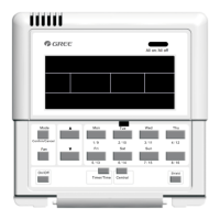
Centralized Controller
16
(7) In step
⑦
, connect the communication cords to G1, G2 terminals, and connect
the neutral wire and live wire to the N, L terminal; connect the ground wire to
position on the electric box rear cover. Secure it with screw M4
×
12.
(8) In step
⑧
, locate the controller’s rear cover onto the electric box rear cover
with screw ST4.2
×
9.5 MC.
(9) In step
⑨
, connect the wire between touch screen and controller’s rear cover.
3.4 Removal Procedure
Fig.3.14 Diagram of Removal
4 Display and Working Instructions
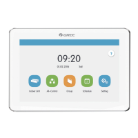
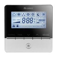
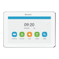
Fig.4.1 Main Page
 Loading...