EasyManua.ls Logo

Gree CE54-24/F(C) - User Manual

Gree CE54-24/F(C)
22 pages
Print Icon
To Next Page IconTo Next Page
Loading...
Owner's Manual
Thank you for choosing Air Conditioners, please read this owner’s manual carefully before operation
and retain it for future reference.If you have lost the Owner’s Manual, please contact the local agent or
visit www.gree.com or send email to global@gree.com.cn or electronic version.
GREE reserves the right to interpret this manual which will be subject to any change due to product
improvement without further notice.
GREE Electric Appliances, Inc. of Zhuhai reserves the final right to interpret this manual.
E-Smart Zone Controller
Model:
CE54-24/F(C)
Question and Answer IconNeed help?

Do you have a question about the Gree CE54-24/F(C) and is the answer not in the manual?

Summary

Centralized Controller Installation

Installation Requirements

Specifies communication cord types, standards, sizes, and maximum lengths for different networks.

Wiring Instructions

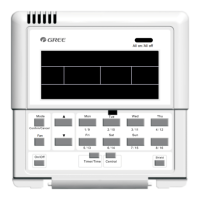
Details port identification and power supply specifications for controller wiring.

Wiring Ports Identification

Explains the meaning of G1, G2, F1, F2, L, N ports on the controller.

Power Supply Specifications

Covers independent power supply, voltage, frequency, power rating, and cord selection.

Connection Methods Overview

Outlines the three methods to connect the controller with the air conditioning system.

Controller Installation Steps

Provides step-by-step instructions for installing the centralized controller.

Controller Removal Steps

Details the steps for removing the centralized controller.

Display and Operation Guide

Main Display and Button Overview

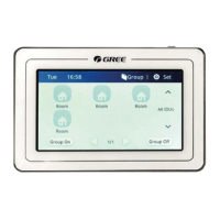
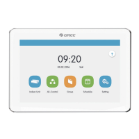
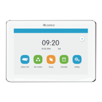
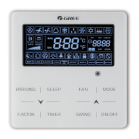
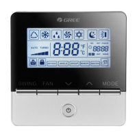
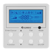
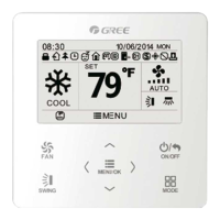
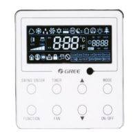
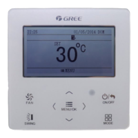
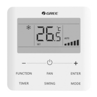
Explains the elements and functions of the main display page and its buttons.

Common Control Buttons

Lists and describes common buttons used for navigation and control.

Touch Screen Button Operation

Explains how to operate buttons on the touch screen interface.

Controller Functions and Settings

All Units On;Off Control

Describes how to turn all connected indoor units on or off using dedicated buttons.

Individual Unit Control

Explains how to access and control individual indoor units.

General Unit Settings

Details basic control parameters like On/Off, Mode, Temperature, Fan Speed, and Swing.

Advanced Unit Features

Covers advanced functions like Sleep, Quiet, Absence, Rapid cooling/heating, and Shielding.

Unit Timer Configuration

Explains how to set timer modes, fan speed, temperature, and ON/OFF times for units.

Grouped Unit Management

Describes how to control groups of indoor units, including editing and adding groups.

Local System Settings

Details local settings such as sound, language, time format, user password, and backlight.

Engineering Unit Setup

Explains how to register and name indoor units for system configuration.

Operational Information and Notices

Provides access to operational information, customer service details, and other notices.

Overview

The GREE E-Smart Zone Controller is a centralized control unit designed for multi VRF air conditioning systems, offering comprehensive management of indoor and outdoor units. This owner's manual provides detailed instructions for installation, display, operation, and various functions, ensuring efficient and effective control of your air conditioning system.

Function Description:

The E-Smart Zone Controller serves as a central interface for managing multiple indoor and outdoor air conditioning units. It allows users to control individual units, groups of units, and the entire system with ease. Key functions include:

  • All ON/OFF Control: Users can turn all indoor units in the current area ON or OFF with a single press of a button. When turned ON, units will operate according to their last memory settings.
  • Single Unit Control: This feature enables detailed control over individual indoor units. Users can adjust operation mode (Cool, Heat, Dry, Fan, Auto, Floor heating, 3D heating, Heat supply), set temperature, and control fan speed and swing functions (Up&Down, Left&Right). Advanced control parameters such as Sleep, Quiet, Auto Quiet, E-Heater, Absence, Rapid, and Energy Saving functions are also available for individual units.
  • Group Control: The controller supports the creation and management of groups of indoor units. Users can add new groups, edit existing groups (including setting group names and adding/removing indoor units), and delete groups. Control parameters for groups are similar to those for single units, allowing for synchronized operation of multiple units. A single indoor unit can be assigned to up to 5 groups.
  • Timer Setting: The controller offers a robust timer function for scheduling ON/OFF times for units. Users can set specific ON/OFF times, select repeat days (Mon, Tue, Wed, Thu, Fri, Sat, Sun), and configure timer mode, fan speed, and set temperature.
  • Local Setting: This section allows for customization of controller settings, including sound, language, temperature unit (°C/°F), time format (12hr/24hr clock), date and time, user password activation/inactivation, backlight settings, and customer service information.
  • Engineering Setting: Designed for professional engineering staff, this section includes indoor unit registration and name setting. Users can register up to 32 indoor units and customize their names and icons for easy identification on the main page.
  • Operation Notice: Provides access to information regarding local unit status, customer service details, operation instructions, and other important notices.
  • Malfunction View: If an indoor unit experiences a malfunction, an "Error" icon will be displayed, allowing users to view detailed information about the issue.

Important Technical Specifications:

  • Power Supply: The centralized controller requires an independent power supply.
    • Input Voltage Range: 110~240VAC
    • Frequency Range: 50/60Hz
    • Maximum Rated Power: 3W
  • Communication Cord (IDU Network):
    • Cord Type: (60227 IEC52/60227 IEC53) Shielding light/Ordinary polyvinyl chloride sheathed cord.
    • Cord Standard: IEC60227-5:2007
    • Cord Size: ≥2×0.75 mm²
    • Total Length of Communication Wire L(m): ≤1000m (If cord size is 2×1mm², communication cord can be stretched longer, but the total length can't exceed 1500m).
    • Note: Circular cord with twisted cores is required. Shielded wire is necessary in places with intense magnetic fields or strong interference.
  • Communication Cord (ODU Network):
    • Cord Type: (60227 IEC52/60227 IEC53) Shielding light/Ordinary polyvinyl chloride sheathed cord.
    • Cord Standard: IEC60227-5:2007
    • Cord Size: ≥2×0.75 mm²
    • Total Length of Communication Wire L(m): ≤250m
  • Power Cord:
    • Cord Type: Single-core soft conductive unsheathed cord (60227 IEC 08)
    • Cord Standard: IEC 60227-3 2007
    • Cord Size: 1.5 mm²
  • Control Capacity: One centralized controller can control up to 16 sets of outdoor unit systems and up to 32 sets of indoor units.
  • Dimensions:
    • Centralized Controller: 128mm (width) x 86mm (height) x 37.7mm (depth)
    • Wiring Box: 86mm (width) x 88.5mm (height) x 46.5mm (depth)

Usage Features:

  • Capacitive Touch Screen: The controller features a capacitive touch screen for intuitive operation.
  • User-Friendly Interface: The main page displays system time, area name, IDU icons with current operation mode and set temperature, and quick access buttons for group control and settings.
  • Page Navigation: For a large number of indoor units, the display supports sliding left or right to turn over pages.
  • Area Switching: A dedicated button allows users to switch between different control areas.
  • Icon-Based Operation: Many functions are represented by clear icons, making them easy to understand and operate.
  • Text and Icon + Text Buttons: Provides flexibility in interaction, allowing users to press text buttons for specific pages or icon+text buttons for functions.
  • Zone Buttons: On the timer page, rectangular frames act as zone buttons for quick access to timer settings.
  • Master IDU/Error/Shield Status Icons: Visual indicators on the IDU display show if a unit is a master IDU, has an error, or is shielded, with a priority display order of master IDU > error > shield.
  • Backlight Adjustment: Users can set the timeout period for the screen backlight and adjust its brightness.
  • Sleep Mode: The controller enters sleep mode when the backlight timeout period is over, and can be woken up by touching any part of the screen or the touch button.
  • Reset Function: A reset option is available to restore local settings, group settings, schedule settings, names and icons of indoor units, and other ex-factory default settings. Holding the Touch Button for 5 seconds also resets the controller.

Maintenance Features:

  • Communication Cord Selection: Strict guidelines for communication cord type, standard, and size must be followed to ensure proper communication and prevent malfunctions.
  • Power Cord Replacement: The supply cord can only be replaced by the manufacturer or an accredited service agent.
  • Installation Procedures: Detailed step-by-step instructions are provided for installation, including preparing the installation hole, pulling out wires, securing the wiring box, and connecting communication and power wires.
  • Removal Procedures: Instructions for safely removing the controller are also included.
  • DIP Switch Settings: Clear guidance on setting the centralized control address DIP switch (SA2_Addr-CC) for different refrigerating systems, especially for ODU network connections, to avoid address conflicts.
  • Matching Resistance: Instructions specify when a matching resistance must be connected between G1 and G2 ports, particularly when the controller is connected to the ODU network or the last indoor unit of the IDU network.
  • Environmental Considerations: Warnings against installing the controller in places with corrosive gas, dust, salt mist, oil smoke, wet/damp conditions, direct sunlight, high temperatures, or where it might be splashed by water.
  • Power Cut-off during Installation: Emphasizes the importance of cutting off the power supply to the indoor unit throughout the entire installation process.
  • Screen Protection: Caution to avoid damaging the touch screen during installation and to prevent scratching it with hard or sharp objects during operation.
  • Wiring Integrity: Instructions to ensure communication and power wires are led separately from the wire orifice of the electric box rear cover.

Gree CE54-24/F(C) Specifications

General IconGeneral
BrandGree
ModelCE54-24/F(C)
CategoryController
LanguageEnglish

Related product manuals