This document is the owner's manual for the GREE Wired Controller XK49, designed for Commercial Air Conditioners. It provides comprehensive information on the device's display, buttons, installation, commissioning, operation, and error codes.
Function Description
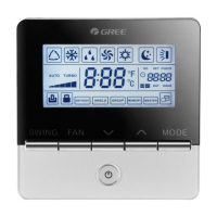
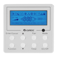
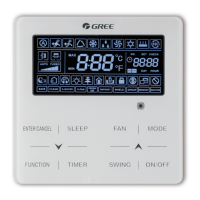
The GREE Wired Controller XK49 serves as a central control unit for commercial air conditioning systems. It allows users to manage various operational aspects of indoor units, including mode selection, temperature setting, fan speed adjustment, and advanced functions like child lock and gate control. The controller can operate in different configurations, from controlling a single indoor unit to managing multiple units simultaneously, and can also function as a master or slave controller within a network. It features an LCD display for clear visualization of settings and status, and a set of buttons for user interaction. The device is also equipped with a gate control interface, enabling integration with building management systems for automatic unit on/off control based on card insertion or removal.
Important Technical Specifications
- Communication Line: The total length of the communication line between the indoor unit and the wired controller should not exceed 250m. It requires a 2-core twisted pair cord, specifically Light/Ordinary polyvinyl chloride sheathed cord (60227 IEC 52 / 60227 IEC 53) with a wire size of 2x0.75~2x1.25 mm². For environments with intense magnetic fields or strong interference, shielded wire is recommended.
- Group Control Capacity: One wired controller can control up to 16 indoor units simultaneously, provided they are of the same series and within the same indoor unit network.
- Wired Controller Addressing: When two wired controllers control one or more indoor units, their addresses must be different (01 for master, 02 for slave). Only one master wired controller is allowed in such a setup.
- Gate Control Power Input: The gate control card insertion/removal device supports AC 100-240V~50/60Hz or DC 5~24V power input.
- Temperature Setting Range: In Cooling, Fan, Heating, and Dry modes, the temperature can be set between 16°C and 30°C.
- Static Pressure Levels: The indoor fan motor supports various static pressure levels (01-09), with 5-level and 9-level options depending on the indoor unit model. The wired controller automatically selects the appropriate range.
- Clock Timer Repetition: The clock timer can be set to "once" or "repeat everyday."
- High Ceiling Installation: Supports settings for standard height (00) and high ceiling (01) installations for cassette units.
- Air Return Plate: Features settings for different angles of air return plate (01: angle 1 (25°), 02: angle 2 (30°), 03: angle 3 (35°)).
- Air Outlet Temperature Setting (Fresh Air Indoor Unit): For Fresh Air Indoor Units, the air outlet temperature can be set between 16°C and 30°C.
- Union Setting (Fresh Air Indoor Unit): Supports union control (01) or no union control (00).
Usage Features
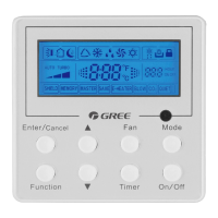
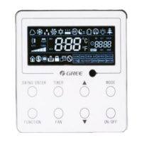
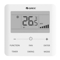
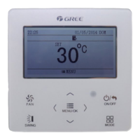
- Display: The LCD displays various icons and values, including operating mode (Auto, Cooling, Dry, Fan, Heating), fan speed (Auto, Low, Medium-low, Medium, Medium-high, High, Turbo), set temperature, project number, indoor unit quantity, outdoor unit defrosting status, child lock status, and gate control function. It also shows error codes and status codes for troubleshooting.
- Buttons: The controller features buttons for SWING, FAN, ON/OFF, and MODE. The "∧" and "∨" buttons are used for adjusting parameters and navigating menus.
- Operation Modes: Supports Auto, Cooling, Dry, Fan, and Heating modes. In Auto mode, the indoor units automatically select the operating mode based on temperature changes.
- Temperature Setting: Allows precise temperature adjustment in 1°C increments or rapid adjustment by holding the "∧" or "∨" buttons.
- Fan Speed Setting: Users can cycle through various fan speeds (Auto, Low, Medium-low, Medium, Medium-high, High, Turbo) using the FAN button. In Dry mode, fan speed is fixed at low. For Fresh Air Indoor Units, fan speed is fixed at high.
- Swing Function: Activates or cancels the up and down swing function.
- Child Lock: A safety feature that locks the controller buttons, activated by simultaneously pressing the "∧" and "∨" buttons for 5 seconds.
- Gate Control: Enables automatic on/off control of the unit(s) by inserting or removing a card from a connected gate control system.
- Parameter Viewing: Users can access a parameter viewing interface by long-pressing MODE and SWING buttons for 5 seconds to check various unit parameters like indoor ambient temperature, filter clean reminder time, wired controller address, indoor unit quantity, outdoor ambient temperature, indoor relative humidity, and air outlet temperature of Fresh Air Indoor Units.
- Parameter Setting: Allows configuration of parameters such as master/slave status of the indoor unit, infrared receiver activation, wired controller address, quantity of group control indoor units, temperature unit (Celsius/Fahrenheit), static pressure level, high ceiling installation, clock timer repetition, cooling/heating setting temperature under Auto mode, set priority operation, clear filter accumulated time, and air return plate angle.
Maintenance Features
- Error Code Display: The LCD displays specific error codes for both outdoor and indoor units, facilitating quick diagnosis of malfunctions. Error codes cover a wide range of issues, including compressor protection, sensor errors, communication errors, fan drive board errors, and more.
- Status Code Display: Provides status codes that indicate the current operational state of the unit, such as "Unit is waiting for debugging," "Check the compressor operation parameters," "Defrosting," and "Online Testing."
- Filter Clean Reminder: The controller can display a reminder for filter cleaning, although the filter-clean reminder function is not available for this specific wired controller model.
- Troubleshooting: The manual provides detailed lists of error codes and status codes, which are crucial for technicians to identify and resolve issues. For example, "E1" indicates High Pressure Protection, "L0" indicates Indoor Unit Error, and "A3" indicates Defrosting.
- Installation Requirements: Strict guidelines for installation are provided to prevent malfunctions, including avoiding wet places, direct sunlight, high-temperature objects, water-splashing areas, and locations facing windows to prevent interference.
- Wiring Requirements: Detailed instructions for communication line selection and wiring methods between the wired controller, indoor units, and gate control system are provided to ensure correct setup and reliable operation. This includes specifications for wire type, length, and the importance of shielded wire in noisy environments.
- Disassembly Instructions: The manual includes a diagram and steps for disassembling the wired controller, which may be necessary for maintenance or replacement.