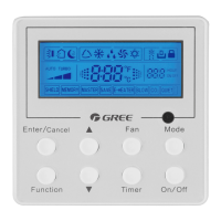
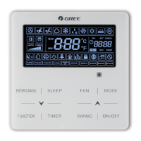
Wired Controller XK49
2
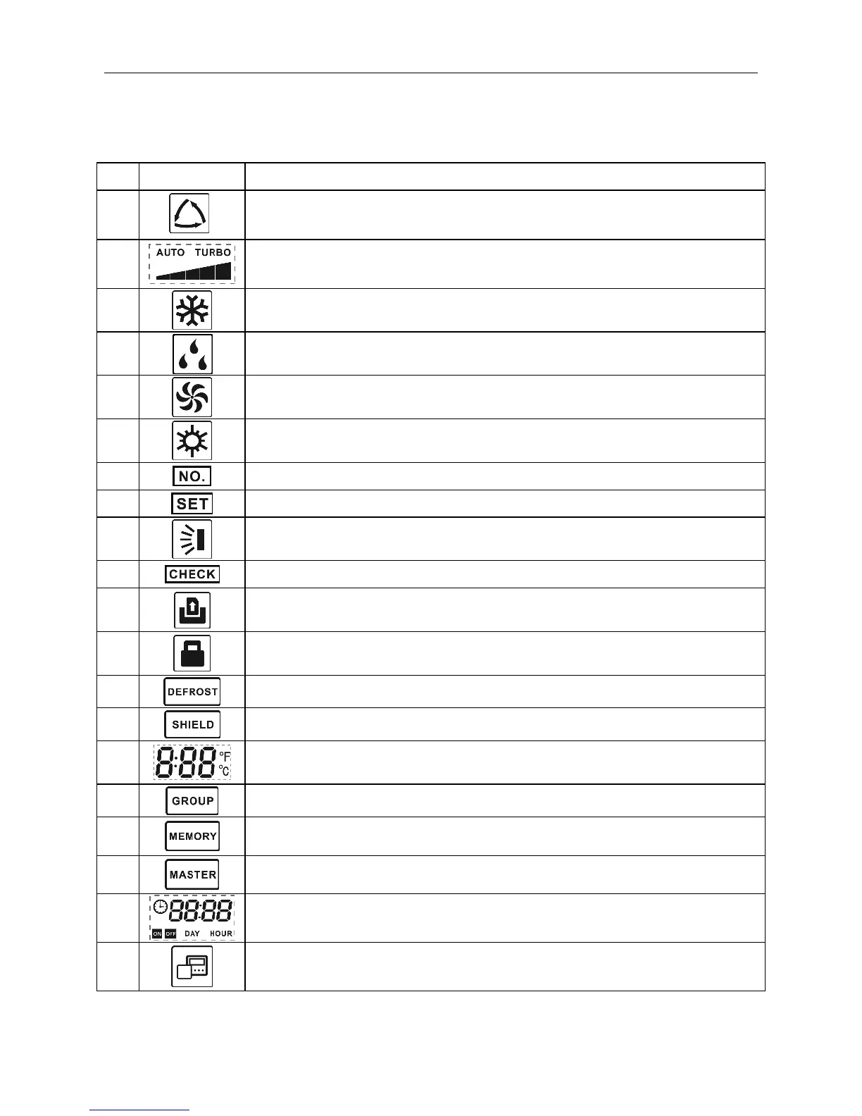
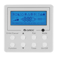
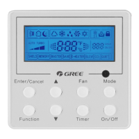
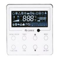
1.2 LCD Display Instruction
Table 1.1 LCD display instruction
Auto mode (Under Auto mode, the indoor units will automatically select their
operating mode as per the temperature change so as to make the ambient
comfortable.)
Current set fan speed (including auto, low speed, medium-low speed, medium
speed, medium-high speed, high speed and turbo seven status)
When inquiring or setting project number of indoor unit, it displays "NO." icon
Display "SET" icon under parameter setting interface
Up and down swing function
Display "CHECK" icon under parameter view interface
Outdoor unit defrosting status
It shows the setting temperature value(In case the wired controller is controlling a
Fresh Air Indoor Unit, then the temperature zone will display FAP)
One wired controller controls multiple indoor units
Memory status (The indoor unit resumes the original setting state after power
failure and then power recovery)
Current wired controller connects master indoor unit
The data display area will help to show the parameters checked or set.
It indicates the current wired controller is the slave wired controller
(address of wired controller is 02)