20
Installation and Maintenance
Service Manual
9. Installation Instructions
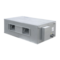
These duct
type indoor units are limited to be installed for one room.
9.1 Installation of Indoor Unit
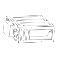
9.1.1 Outline Dimension and Installation Spots
Equip with a inspection hatch after lifting the unit. For the convenience of maintenance, the
service port should be on one side of the electric box and below unit’s lower level.
Fig 9.1.1
Below are dimensions of A, B, C, etc. for different models:
Unit:mm(in.)
Model A B C D E F G
740
(29-1/8)
500
(19-11/16)
830
(32-11/16)
300
(11-13/16)
754
(29-11/16)
700
(27-9/16)
700
(27-9/16)
1040
(40-15/16)
500
(19-11/16)
1130
(44-1/2)
300
(11-13/16)
754
(29-11/16)
1000
(39-3/8)
700
(27-9/16)
DUCT09HP230V1BD
DUCT12HP230V1BD
DUCT18HP230V1BD
GFH(21)DB-D3DNA1A/I
DUCT24HP230V1BD
9.1.2Suspend the indoor unit
(1) Drill bolt holes and install bolts
1) Stick the reference cardboard on the installation position; drill 4 holes according to the
hole site on the cardboard as shown in fig 4.1.3; diameter of drilling hole is according
to the diameter of expansion bolt and the depth is 60-70mm(2-3/8~2-3/4 in.), as
shown in fig 4.1.4.
Unit: mm(in.)
 Loading...