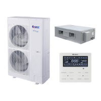
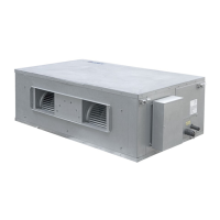
GREE Duct type split Air conditioner Inverter Series
74
Flow-process diagram of debugging:
01
:
Set master unit
02:Allocate addresses
03:Confirm the quantity of ODU
04:Confirm the quantity of IDU
07:Detect indoor components
06:Detect outdoor components
05:Detect ODU’s internal communication
08:Confirm preheated compressor
09:Confirm status of valve of ODU
10:Debugging completed status
1.4.4 Debugging process
(1) Unit manufactured before Oct 30,2018.
Debugging procedure for test run, display instruction for indicator on main board of outdoor unit and
operation method are as below:
Description of each stage of debugging progress
—— Debugging Code
Instruction for Code and Operating Method
Progress
LED
Display Code
Start A0
No debugged yeat. Press “SW3” button consecutively in the
master module for over 5s to enter auto debugging.
01_ Set master
unit
01/CC
Display
repeatedly
There is no master unit in the system.
The system cannot continue to conduct debugging, and all the
buttons are invalid that must be reset by cutting the power.
01/CF
Display
repeatedly
There are two or more master units in the system.
The system cannot continue to conduct debugging, and all the
buttons are invalid that must be reset by cutting the power.
Please set the correct “SA6” DIP switch.
01/oC
Display
repeatedly
There is only one master unit in the system.
The unit will automatically enter into the next step after
displaying for once.
 Loading...