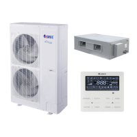
GREE Duct type split Air conditioner Inverter Series
80
1.5.5 Energy conservation operation setting
The function enables the unit to operate in energy conservation mode, after entering function setting
(n0), main board indicator of outdoor unit is displayed as follows:
LED
Function code Display method
01/02 Blink
Select corresponding quiet mode through “SW1” and “SW2”, short press “SW3” to confirm the
selected mode.
Note: the defaulted factory setting is “capacity comes first”, namely “01”, which means the capacity shall
control preferentially, “02” means the master control unit will memorize the setting after setting energy
conservation control preferentially, and the setting will not be cleared after re-energization.
1.5.6 Reset factory setting
(1) Reset defaulted factory setting 1 (clear all settings):
Long press “SW1 + SW4” button for over 10s in the main module, the nixie tube will display “oC” for
3s, the main board will remove all settings, including IP address of indoor and outdoor unit.
(2) Reset defaulted setting 2 (clear all settings other than project debugging status):
Long press “SW2 + SW4” for over 10s in the main module, the nixie tube will display “oC” for 5s, the
main board will remove all settints, including IP address of indoor and outdoor unit, but completion label
for project debugging and the memory of indoor and outdoor unit quantity shall be kept.
(3) Reset defaulted setting 3 (clear function setting of outdoor unit only):
Long press “SW3 + SW4” for over 10s in the main module, the nixie tube will display “oC” for 7s,
then clear all function settings of the system, but project code of indoor and outsoor unit, the memory of
indoor and outdoor unit quantity and completion label for project debugging shall be kept.
2 Troubleshooting
Content
Content
Content
L0
Malfunction of
indoor unit
L9
unit for one-to-more
d8
Malfunction of water
temperature sensor
L1
LA
Wrong series for one-to-
more indoor unit
d9 Malfunction of jumper cap
L2
LH
Alarming due to bad air
quality
dA
Abnormal address for
indoor unit
L3
Water overflow
protection
LC
can’t match with outdoor
dH
Abnormal PCB for wired
controller
L4
of wired controller
d1 Poor indoor PCB dC
Abnormal code-dialing
setting of capacity
L5
Freeze prevention
protection
d3
Malfunction of ambient
temperature sensor
dL
exhause temperature
L6
Mode shock
d4
Malfunction of entry tube
temperature sensor
dE
2
L7
d6
Malfunction of exit tube
temperature sensor
C0
Communication
malfunction
L8
Insufficient power
supply
d7
Malfunction of humidity
sensor
AJ Clean alarming for filter
db Special code: engineering debugging code
 Loading...