24
Floor Ceiling Type Fan
Coil Unit Service Manual
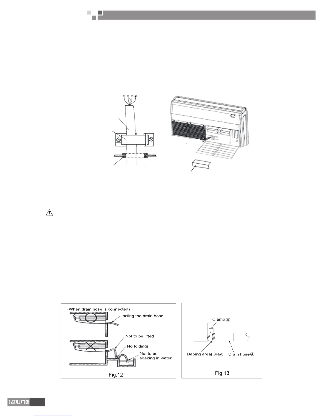
4 Electrical wiring
(1) Open the surface panel.
(2) Remove the electrical box cover.
(3) Route the power connection cord from the back of the indoor unit and pull it toward the front thought
the wiring hole for connection.
(4) Connect the wires of the power connection cord and valve connection cord as circuit diagram.
(5) Reassemble the electrical box cover.
(6) Recover the surface panel.
Fig.11
Rubber bush
Wiring clamp
Power connection
cord and valve
connection cord
Electrical box cover
Fig.12
5 Drain piping work
CAUTION:Make sure the drain ows out .
(1) Drain piping
1) The drain pipe outlet direction can be chosen from either the right rear or right.
2) The diameter of the drain pipe should be equal to or greater than the diameter of the connecting pipe.
(Vinyl tube; pipe size:20 mm; outer dimension:26 mm)
3) Keep the drain pipe short and incline downwards at a gradient of at least 111 00 to prevent air pockets.
(Refer to Fig.12)
4) Use the attached drain hose.
④
and clamp
⑤ .
Insert the drain hose completely into the drain socket.
Tighten the clamp within the range of gray tape until the screw head is less than 4 mm from the hose.(Refer to
Fig.13,14)
5) Wrap the attached sealing pad OD over the clamp and drain hose to insulate. (Refer to Fig.14)
6) No folding of drain hose inside the unit. (Refer to Fig.15)
(2) Conrm that smooth drainage is achieved after the piping work.
Pour 600 cc of water into the drain pan from the air outlet for conrming drainage.(Refer to Fig.16)
 Loading...