
N
Nicholas PhamJul 26, 2025
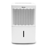
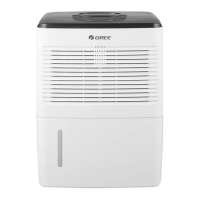
What to do if there is water in the bucket when using drain hose with Gree GDN20BD-K5EBA1A?
- MMrs. Kathleen JohnsonJul 26, 2025
If you notice water in the bucket while using the drain hose with your Gree Dehumidifier, first, ensure the drainage joint is well connected. Second, check the drain hose for any obstructions and clear them. Finally, remove the drain hose and reinstall it, making sure it's correctly attached.