DC Inverter Multi VRF System User Manual
20
necessary to perform test operation and debugging. Otherwise, unit won’t be able to work.
2. Test operation and debugging must be performed by professional technicians or under the
guidance of professional technicians.
5.2.1 Prepare the test operation and debugging
(1) Do not connect power until all installation work is finished.
(2) All control circuits and wires are correctly and securely connected.
(3) Check whether the fixing loops for compressor foots are removed.
(4) All small pieces, especially metal chips, thread ends and forceps holder, must be removed
from the unit.
(5) Check whether unit’s appearance and pipeline system has been damaged during
transportation.
(6) Calculate the quantity of refrigerant that needs to be added according to the pipe length.
Pre-charge the refrigerant. In case that the required charging quantity is not reached while
refrigerant can’t be added, record the quantity of refrigerant that still needs to add and
complement the quantity during test operation. For details of adding refrigerant during test
operation, see below.
(7) After refrigerant is added, make sure valves of outdoor unit are completely open.
(8) For the convenience of troubleshooting during debugging, unit shall be connected to a PC
with applicable debugging software. Make sure unit’s real-time data can be checked through
this computer. The installation and connection of debugging software can be found in the
Service Manual.
(9) Before test operation, make sure unit is power on and compressor has been preheated for
more than 8 hours. Touch the unit to check whether it’s normally preheated. If yes, start test
operation. Otherwise, compressor might be damaged.
5.2.2 Test Operation and Debugging
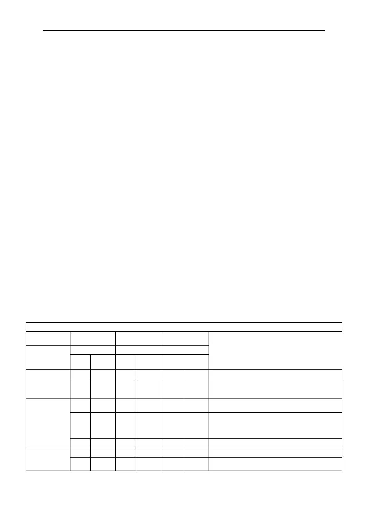
Description of test operation procedures and main board display of ODU
Description of each stage of debugging progress
Code meaning and operation method
Hold main board’s SW7 button for 5s to start
debugging. Main board will display as said in the
left. 2s later, next step starts.
System is allocating addresses. 10s later, display
as below:
No master indoor unit. Display will be on for 1min,
during which master IDU can be set manually. If
not, system will set the unit with minimum IP
address as the master IDU.
Allocation is finished. 2s later, next step starts.
03_ Confirm
the quantity of
ODU
System is confirming. 1s later, next step starts.
System finishes confirmation. 2s later, next step
starts.

 Loading...