DC Inverter Multi VRF System
22
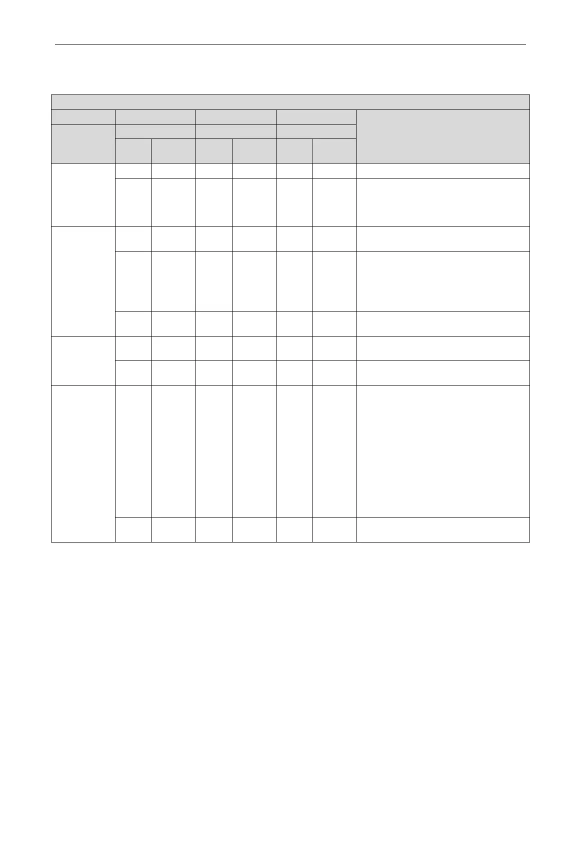
5.2.2 Test Operation and Debugging
Description of test operation procedures and main board display of ODU.
Description of each stage of debugging progress
Code meaning and operation method
Progress
Code
Code
Code
01_Set
master unit
db On 01 On OC On
Hold main board’s SW7 button for 5s to
start debugging. Main board will display
as said in the left.
2s later, next step
02_ Allocate
addresses
db On 02 On Ad Blink
System is allocating addresses. 10s
db On 02 On L7 Blink
No master indoor unit. Display will be on
for 1min, during which master IDU can
be set manually. If not, system will set
the unit with minimum IP address as the
db On 02 On OC On
Allocation is finished. 2s later, next step
03_ Confirm
the quantity
of ODU
db On 03 On 01 Blink
System is confirming. 1s later, next step
db On 03 On OC On
System finishes confirmation. 2s later,
04_ Confirm
the quantity
of IDU
db On 04 On 01~80 Blink
LED3 displays the quantity of indoor unit.
Confirm the number manually. If the
number is not consistent with the display
one, cut off power of IDU and ODU and
check whether communication wire of
IDU is correctly connected. After the
check, connect power and start
debugging from progress 01. If the
number is then correct, press main
board’s SW7 button to confirm.
Then the
db On 04 On OC On
System has confirmed the quantity. 2s
 Loading...

