DC Inverter Multi VRF System
30
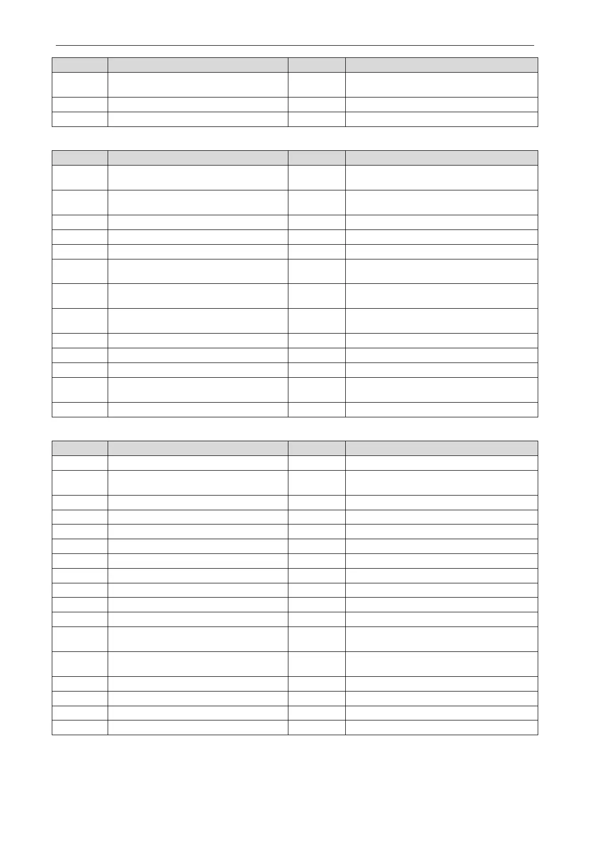
H1
Driving board of fan operates abnormally
H2
Voltage protection of driving board power of
Reset protection of driving module of fan
Drive PFC protection of fan
Over-current protection of inverter fan
Debugging:
U0 Preheat time of compressor is insufficient U2
Wrong setting of ODU’s capacity
code/jumper cap
U4 Refrigerant-lacking protection U5
Wrong address for driving board of
Alarm because valve is abnormal
Short-circuit malfunction of IDU
Malfunction of pipe-line for ODU
Setting of main IDU is successful
Charging of refrigerant is invalid
C0
Communication malfunction between
IDU, ODU and IDU’s wired controller
C2
Communication malfunction between main
control and inverter compressor driver
C3
Communication malfunction between
main control and inverter fan driver
C4 Malfunction of lack of IDU
C5
Alarm because project code of IDU is
inconsistent
C8 Emergency status of compressor
Rated capacity is too high
Malfunction of lack of main control unit
Rated capacity is too low
Malfunction of multiple main control units
Malfunction of multiple main wired controllers
CP
Malfunction of multiple main wired
CU
Communication malfunction between IDU
and the receiving lamp plate
Overflow distribution of IP address
Status:
Unit waiting for debugging
Inquiry of compressor operation parameters
A2
Refrigerant recovery operation of
A3 Defrosting
Heat pump function setting
EU AA level EER test mode
Charging refrigerant automatically
Charging refrigerant manually
Alarm for cleaning filter
Debugging confirmation for startup of unit
Long-distance emergency stop
Emergency stop of operation
SE operation setting of system
n1 Setting of defrosting cycle K1 n2
Setting of upper limit of IDU/ODU capacity
n4
Limit setting for max. capacity/output
n6 Inquiry of project code of IDU
8 Maintenance and Care
Regular check, maintenance and care can extend unit’s service life. Please have specialized
person in charge of the management of air conditioners.
 Loading...

