Gree GMV6 DC Inverter VRF Units Service Manual
295
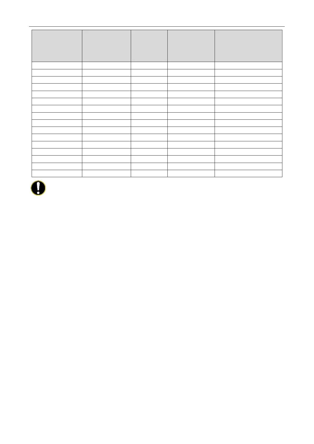
Model Combination method
Capacity of
circuit breaker
of each
combination
Minimum cross-
sectional area of
grounding wire (mm
2
)
Recommended wire (cross-
sectional area) (mm
2
)
4.0×5+10.0×5+10.0×5+10.0×5
6.0×5+10.0×5+10.0×5+10.0×5
6.0×5+10.0×5+10.0×5+10.0×5
6.0×5+10.0×5+10.0×5+10.0×5
10.0×5+10.0×5+10.0×5+10.0×5
10.0×5+10.0×5+10.0×5+10.0×5
10.0×5+10.0×5+10.0×5+10.0×5
10.0×5+10.0×5+10.0×5+10.0×5
10.0×5+10.0×5+10.0×5+10.0×5
10.0×5+10.0×5+10.0×5+10.0×5
10.0×5+10.0×5+10.0×5+10.0×5
10.0×5+10.0×5+10.0×5+10.0×5
NOTES!
① Specification of circuit breaker and power cord is selected on the basis of unit’s maximum power
(max. current).
② Specification of power cord is based on the working condition where ambient temperature is
40°C. and multi-core copper cable (working temperature is 90°C.) is lying on the surface of slot
(IEC 60245). If working condition changes, please adjust the specification according to standard
IEC 60245. Power cord used for outdoor unit should not be below standard 60245 IEC57.
③ Copper-core cable must be used.
④ The engineering wiring should meet the requirements of IEC 60364-5-52 to ensure that the line
voltage drop meets the requirements and the voltage is not lower than the lower limit of the
nominal value of equipment.
⑤ Specification of circuit breaker is based on the working condition where the ambient temperature
of circuit breaker is 40°C. If working condition is different, please adjust the specification
according to national standard
⑥ The circuit breaker should include magnetic trip function and thermal trip function so that system
can be protected from short circuit and overload.
⑦ An all-pole disconnection switch having a contact separation of at least 3mm in all poles should
be connected in fixed wiring.
 Loading...

