GREE DC Inverter Side Discharge VRF Ⅱ for North America
27
4.4.1.3 Installation process
(1) Install .Net Framework 4.0
If your computer has installed .Net Framework 4.0 or versions above, there’s no need to install
again. Otherwise, click “Install .Net Framework 4.0”.
Extracting files
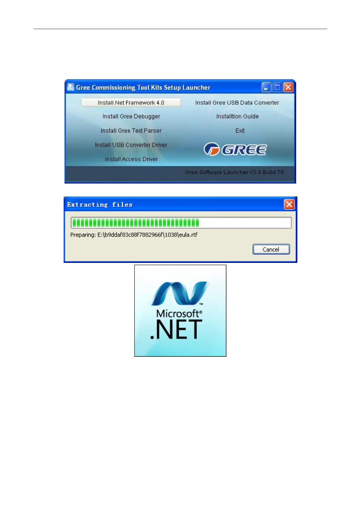 Loading...

