GMV5 DC INVERTER VRF UNITS SERVICE MANUAL
94
If no quit button operations are performed on the master unit for 30 minutes, the function setting
automatically quits and the unit restores the current status.
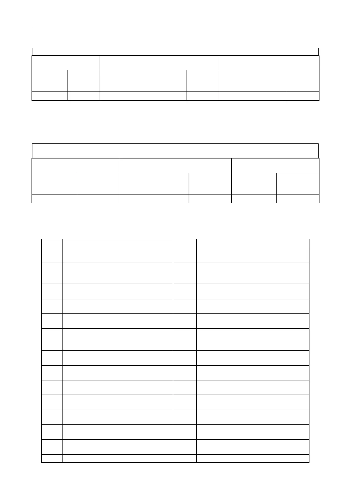
Step 6: If the n9 IDU address query is selected, the display is as follows:
Number of IDUs
(Thousands-place
Hundreds-place)
Number of IDUs
(Tens-place
Ones-place)
The digital LED2 displays the number of IDUs (thousands-place hundreds-place) and the digital LED3
displays the number of IDUs (tens-place ones place). For example, if the number of IDUs is 75, "0075" is
displayed.
If no button operations are performed on the master unit for five minutes, the function setting
automatically quits and the unit restores the current status.
Note: The online IDU quantity query function applies to a single refrigerating system only.
Step 7: If the n6 fault query is selected, the display is as follows. Enter the to-be-confirmed status of fault
query.
Press "SW7" on the master unit to confirm fault query.
Select a fault to be queried by pressing "SW1 (UP)" or "SW2 (DOWN)". LED3 alternately displays the
historical fault code and module address in an interval of one second in the sequence of fault records.
LED2 displays the fault sequence number. If there not historical faults, LED2 and LED3 display ―00‖ by
default. Up to five historical faults can be queried. The faults that can be queried are as follows:
Inverter compressor out-of-step
protection
Communication failure between the
master unit and inverter compressor
driver
Lack of refrigerant protection
Over-high temperature protection for
inverter compressor driver module
Discharge low-temperature protection
Temperature sensor failure of inverter
compressor driver module
Over-low pressure ratio protection
Charge circuit failure of inverter
compressor driver
Over-high pressure ratio protection
DC bus line over-low voltage
protection for inverter outdoor fan
driver
Four-way valve leakage protection
DC bus line over-high voltage protection
for inverter outdoor fan driver
High-temperature protection of
compressor 1
Inverter outdoor fan driver IPM module
protection
High-temperature protection of
compressor 2
Inverter outdoor fan startup failure
Over-current protection of compressor
2
Inverter outdoor fan phase lack
protection
Top high-temperature protection of
compressor 1
Inverter outdoor fan driver module
reset
Top high-temperature protection of
compressor 2
Inverter outdoor fan over-current
protection
DC bus line over-low voltage protection
for inverter compressor driver
Current detection circuit failure of
inverter outdoor fan driver
DC bus line over-high voltage
Inverter outdoor fan out-of-step
 Loading...


