GMV DC Inverter VRF
46
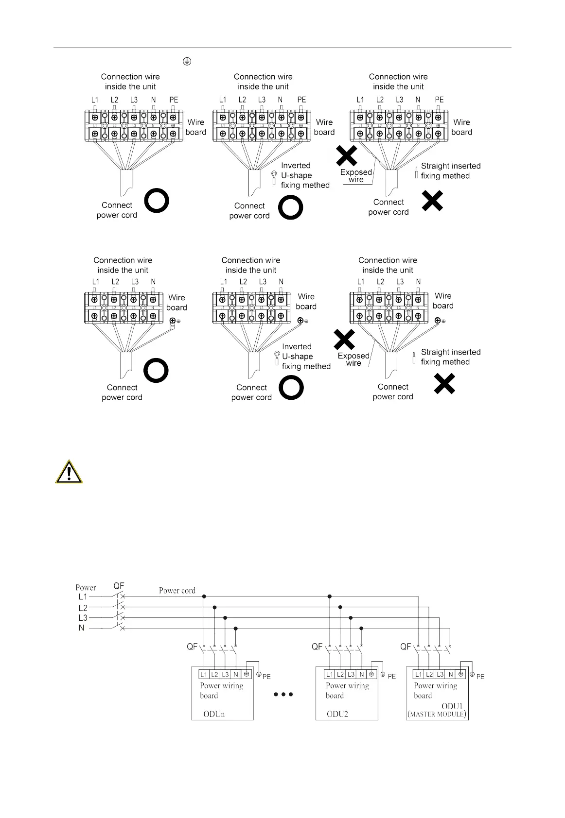
marked with “L1, L2, L3, N,
” respectively and the grounding screw beside the power wiring board.
Fig. 3.8.2
Step 2: Tighten the cable with a cable tie.
Step 3: Please refer to the engineering wiring mark on the unit for the power cord connection.
WARNING!
When the strong wire and the communication line pass through the wire hole, they must be
equipped with wire rubber ring.
3.8.3.2 External Wiring Diagram
Each unit should be equipped with a circuit breaker for short circuit and abnormal overload
protection. The circuit breaker is normally closed.
Fig. 3.8.3
 Loading...