GMV DC Inverter VRF
57
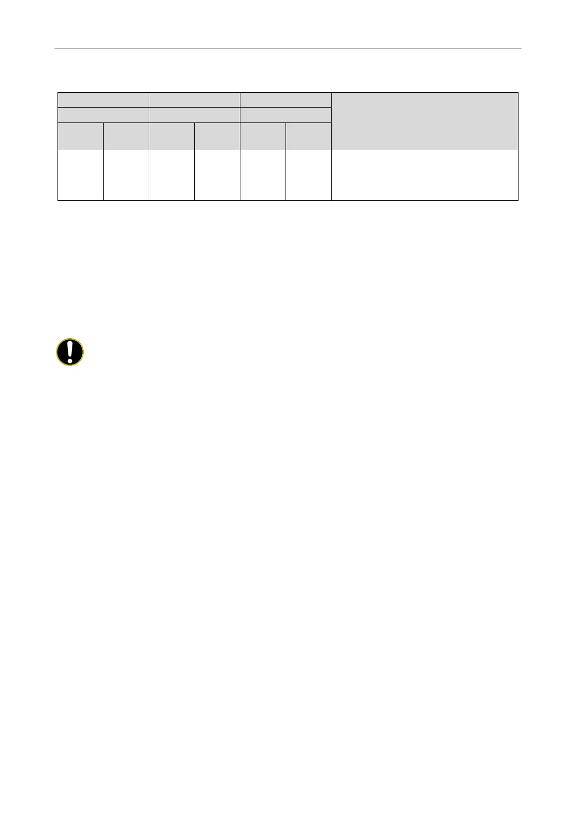
When master module displays as below, the complete unit has conducted the debugging and it
stays at the standby status.
Meaning
Code
Display
Code
Display
Code
Display
01~04 ON OF ON OF ON
he complete unit has conducted the
debugging and the unit is under standby status.
LED1 displays module address; LED2 and
LED3 displays “OF”.
4.3 Basic Introduction for Engineering Debugging
4.3.1 Debugging Method
DC inverter multi VRF unit has three debugging methods at present:
(1) Conduct it by pressing the buttons on the main board of outdoor unit.
(2) Install proprietary software to conduct the debugging through PC. Indoor and outdoor units'
parameters displayed simultaneously through PC software.
(3) Use multi-functional debugger.
NOTE!
As for the detailed operation method for debugging, please refer to corresponding instruction
manual.
4.3.2 Debugging Through the Main Board of Outdoor Unit
When conducting the debugging through the main board of outdoor unit, the main board has the
following debugging operation functions.
Step 1: Cover all the front panels of the outdoor unit and open the debugging window of each
basic module.
Step 2: When the outdoor unit is powered off, set one of the modules as the master module. For
the setting method, see “Master Module DIP Switch Code Setting (SA8_MASTER-S)”.
Step 3: Under the power-on state of the outdoor unit, set the corresponding static pressure
module for the unit according to the design requirements of the outdoor static pressure of the project.
Step 4: The module address is displayed as “01” is the master module. On the master module,
press and hold the SW3 confirmation button for 5 seconds or press the SW3 confirmation button for
more than 10 seconds to enter the unit debugging function.
Step 5: Wait. The unit automatically runs the steps 01 and 02 at this time.
If the master module is set incorrectly in step 01, the following corresponding fault is displayed in
step 01:
 Loading...