GMV DC Inverter VRF
47
NOTE!
The maximum connection number “N” of outdoor unit and the maximum connection number “n”
of indoor unit are decided by the combination method of outdoor unit. For details, please refer to the
part of unit capacity configuration.
3.8.4 Wiring Diagram
Refer to the wiring diagram attached on the unit.
3.9 Communication Line Connection
Adopt CAN bus communication mode between indoor unit and outdoor unit as well among indoor
units.
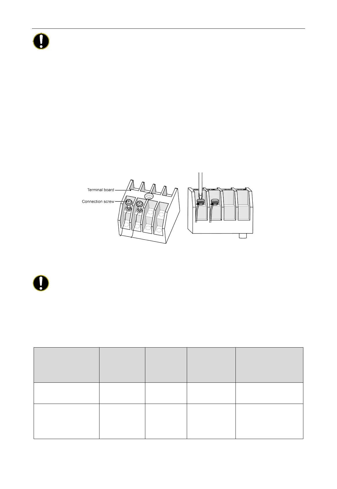
3.9.1 Connection Method of Communication Line Terminal
Communication connections adopts screws for fixing.
Fig. 3.9.1
3.9.2 Communication Material Selection
NOTE!
If the air conditioning unit is installed in a place with strong electromagnetic interference, the
communication line between the indoor unit and the wired controller must adopts shielded wires; the
communication line between indoor units (between indoor unit and outdoor unit) must use the
shielded twisted pairs.
(1) Selection of communication line between indoor unit and wired controller.
Wire type
Length of
communication
line between
indoor unit and
Wire diameter
(mm
2
)
Wire standard Remark
Light / ordinary PVC
sheathed twisted copper
L≤250 2×0.75~2×1.25 IEC 60227-5:2007
The length of
communication line can't
Shielded light/ordinary PVC
sheathed twisted copper
core cord
L≤250 2×0.75~2×1.25 IEC 60227-5:2007
When the installation
environment of the unit is in
strong magnetic or strong
interference, the shielded
 Loading...