Multi Variable Air Conditioners Ducted Type Indoor Unit
17
4.4.3 Installation of the Return Air Duct
(1) The default installation location of the rectangular flange is at the back and the return air
cover plate is at the bottom, as shown in Fig.4.4.6.
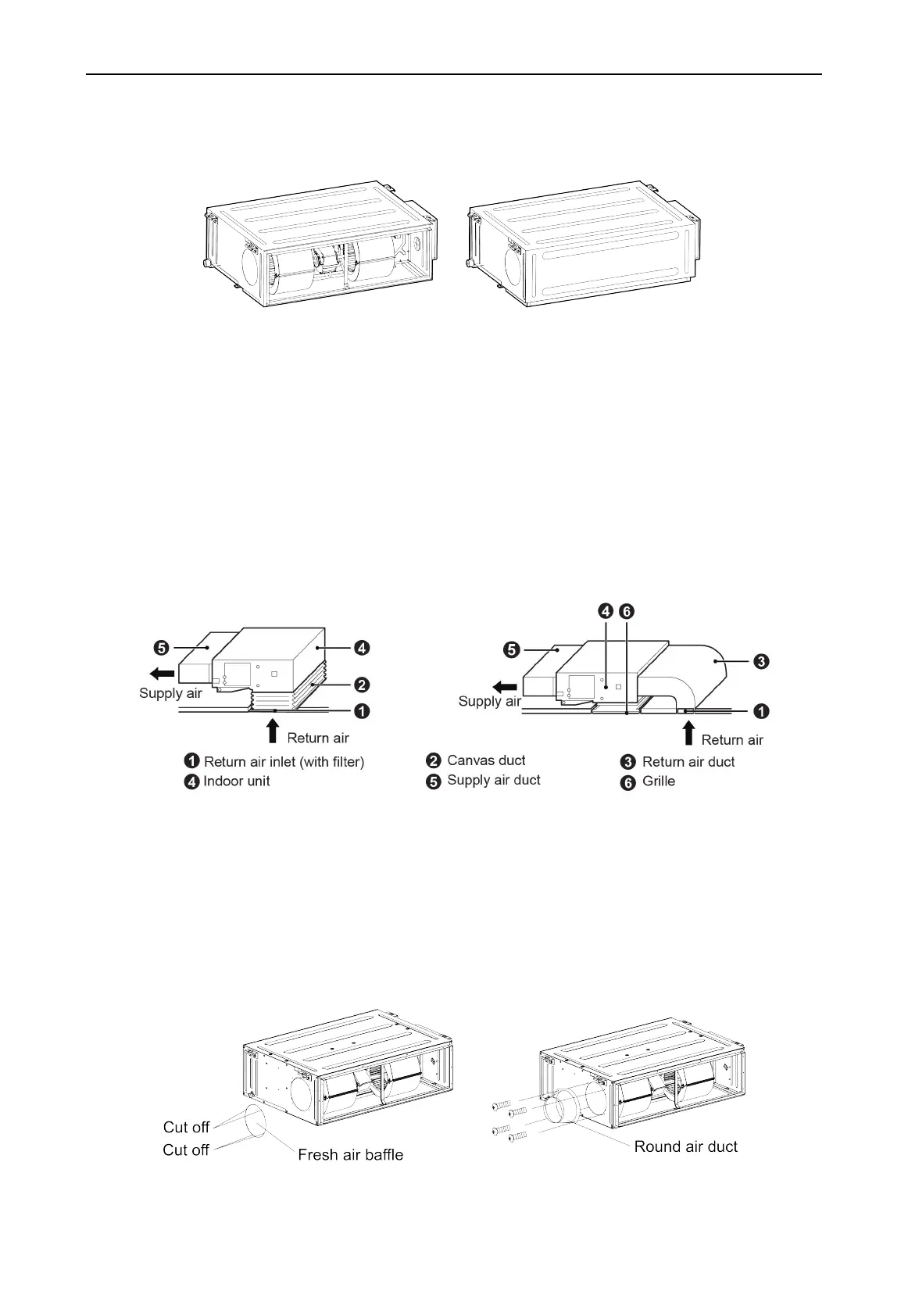
Fig.4.4.6
(2) If the bottom return air is desired, just change the place of the rectangular flange and the
return air cover plate. The bottom return air is only apply to GMV-ND07~54PHS/B-T(U).
(3) Connect one end of the return air duct to the return air outlet of the unit by rivets and the
other to the return air louver. For the sake of the convenience to freely adjust the height, a
cutting of canvas duct will be helpful, which can be reinforced and folded by 8# iron wire.
(4) More noise is likely to be produced in the bottom return air mode than the rear return air
mode, so it is suggestive to install a silencer and a static pressure box to minimize the noise.
(5) The installation method can be chosen with considering the conditions of the building and
maintenance etc., as shown in Fig.4.4.7.
Fig.4.4.7
4.4.4 Installation of the Fresh Air Pipe
(1) When the fresh air pipe is needed to be connected, cut the fresh air baffle as Fig.4.4.8. Plug
up the gap of the fresh air baffle by sponge if the fresh air duct is not be used.
(2) Install the round flange so that the fresh air duct can be connected as Fig.4.4.9.
(3) Sealing and heat preservation should be done for both the air pipe and round flange pipe.
(4) Fresh air should be treated via the air filter.
Fig.4.4.8 Fig.4.4.9
 Loading...