GMV5 Compact Series VRF Outdoor Unit
15
Fig.11 Cut manifold
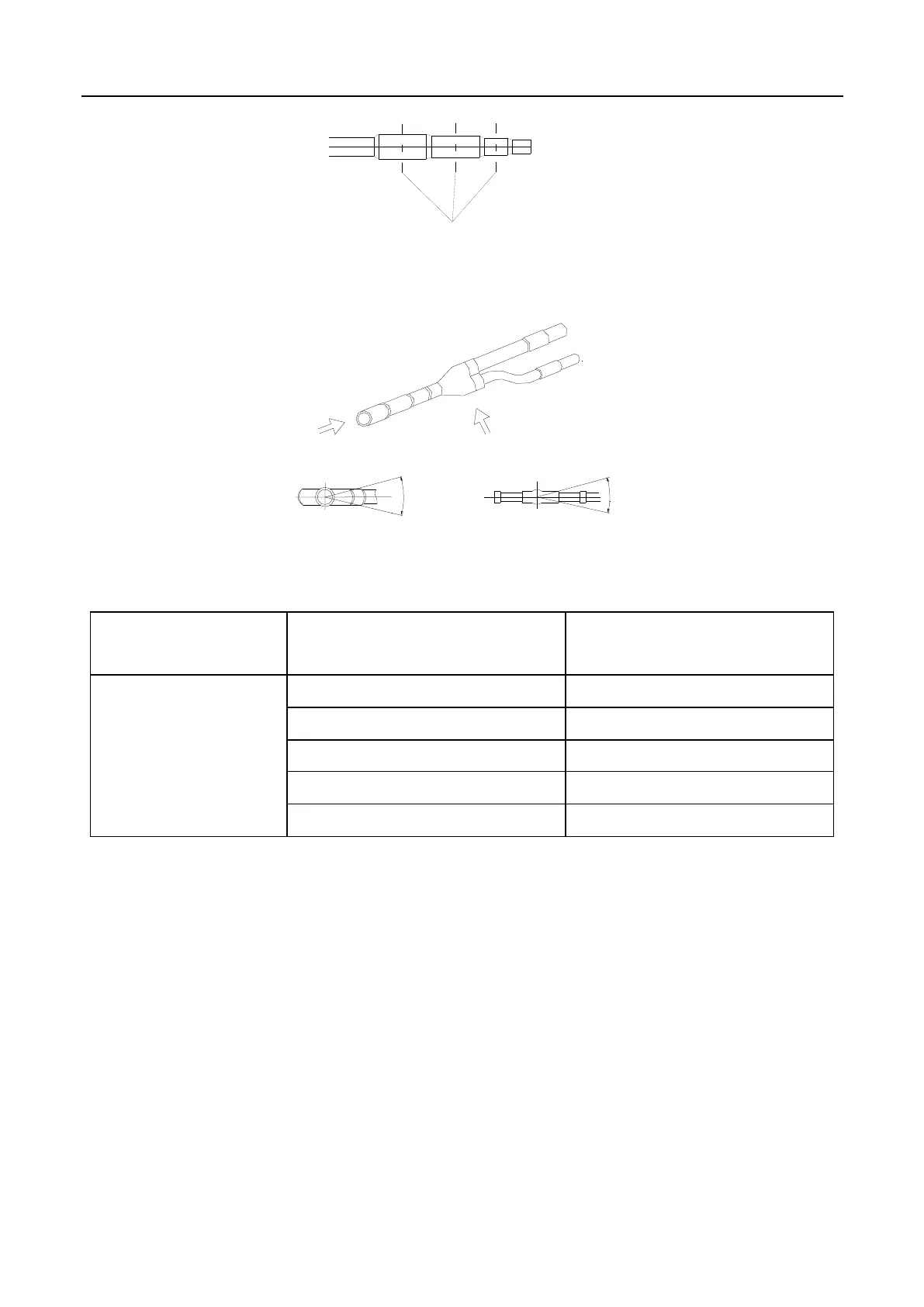
(3) Y-type manifold must be installed vertically or horizontally.
Fig.12 Installation of manifold
Select Y-type manifold:
Total capacity of downstream indoor
units X(KW)
Y-type manifold
(2 branches)
(4) Thermal insulation for manifold
For gas pipe side manifold is isolated by insulating material that can bear 120℃ or higher temperature, and the
foam attached on the manifold cannot be taken as insulating material. For liquid pipe side the foam attached on
the manifold and the field insulating material should be in touch in case of dropping dew.
4.4.3 Thermal Insulation for Pipeline
(1) For multi-VRF system, every copper pipe should be labeled so as to avoid misconnection;
(2) At the manifold inlet, at least leave 500mm straight pipe section, and for FQ04 manifold, keep it at least
800mm;
(3) Every 6m drop height between indoor and outdoor units, one oil loop should be set on gas pipe so as to keep
normal oil return;
(4) Thermal insulation for pipeline.
1) To avoid condensate or water leakage on connecting pipe, gas pipe and liquid pipe must be wrapped with
 Loading...


