Gree GMV6 DC Inverter VRF Units Service Manual
302
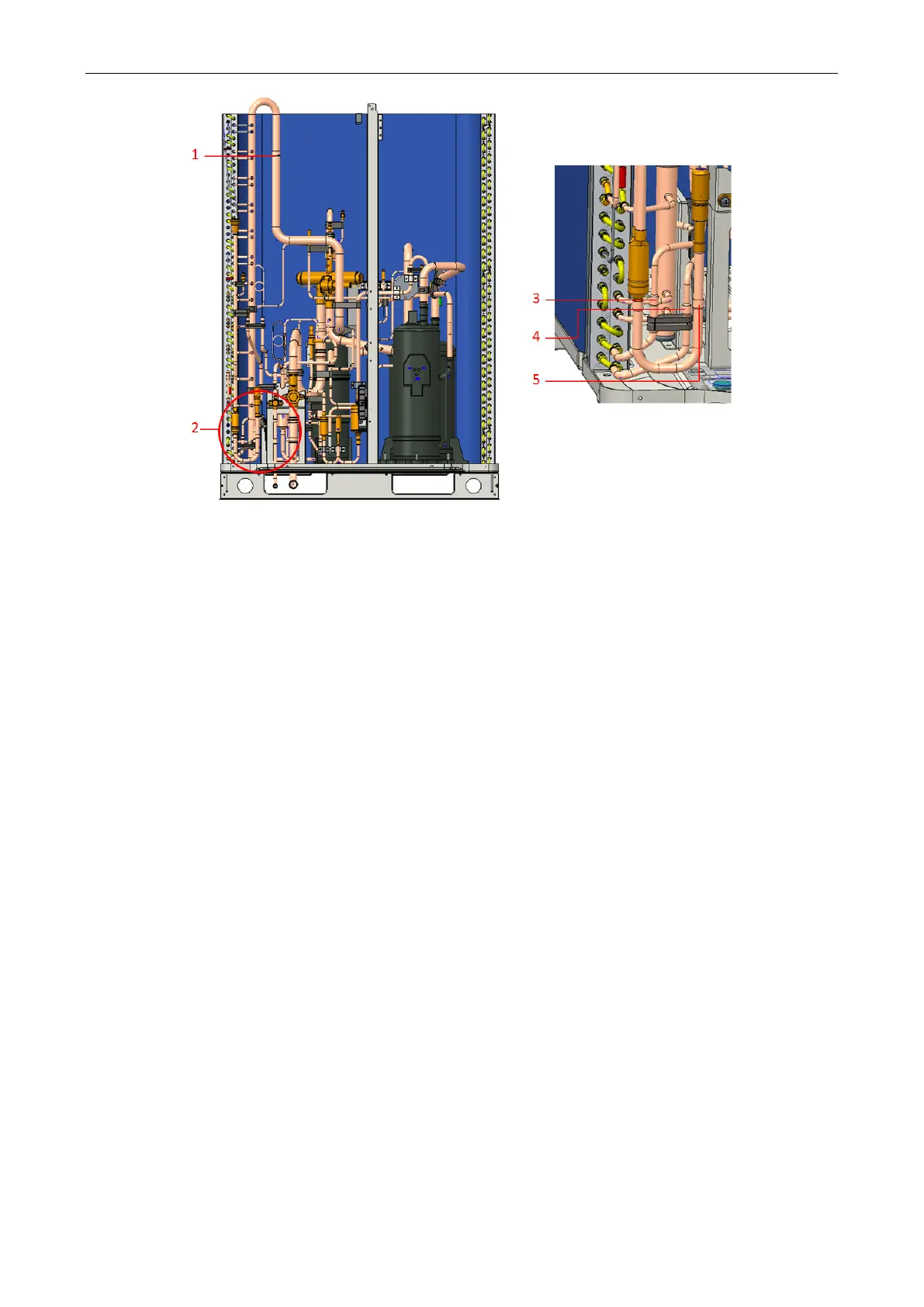
1 — connection point 2 — three connection points (3, 4, 5)
(7) Pull it off the compressor after using gas welding to heat the inlet and outlet pipes. Adopt nitrogen
protection during welding. The nitrogen pressure is 0.5±0.1kgf/cm
2
(relative pressure). When
heating, do not burn the surrounding materials.
(8) Remove the condenser from the chassis.
Installation procedure
(1) Place the new condenser in the correct position.
(2) Fix the two screws that connect the condenser to the chassis.
(3) Install the left side panel, the right side panel, the upper cross beams (two in front and rear), and
the grille (rear) in sequence.
(4) Place the electrical appliance box in the correct position and tighten the screws.
(5) Weld the four connection points of the condenser and pipeline system and the two refrigerant
tubes of the radiator of the box. Adopt nitrogen protection during welding. The nitrogen pressure
is 0.5±0.1kgf/cm
2
(relative pressure). Note: When welding, do not get the other components
burnt.
(6) Install the fan, the baffle ring, the top cover assembly, the upper cover (front), and the upper
cover (rear) in sequence.
(7) Make sure that the components and cables are properly connected.
(8) After checking that there is no problem, buckle the front panel and tighten the screws.
 Loading...


