GREE U-Match 5 SERIES UNIT SERVICE MANUAL
38
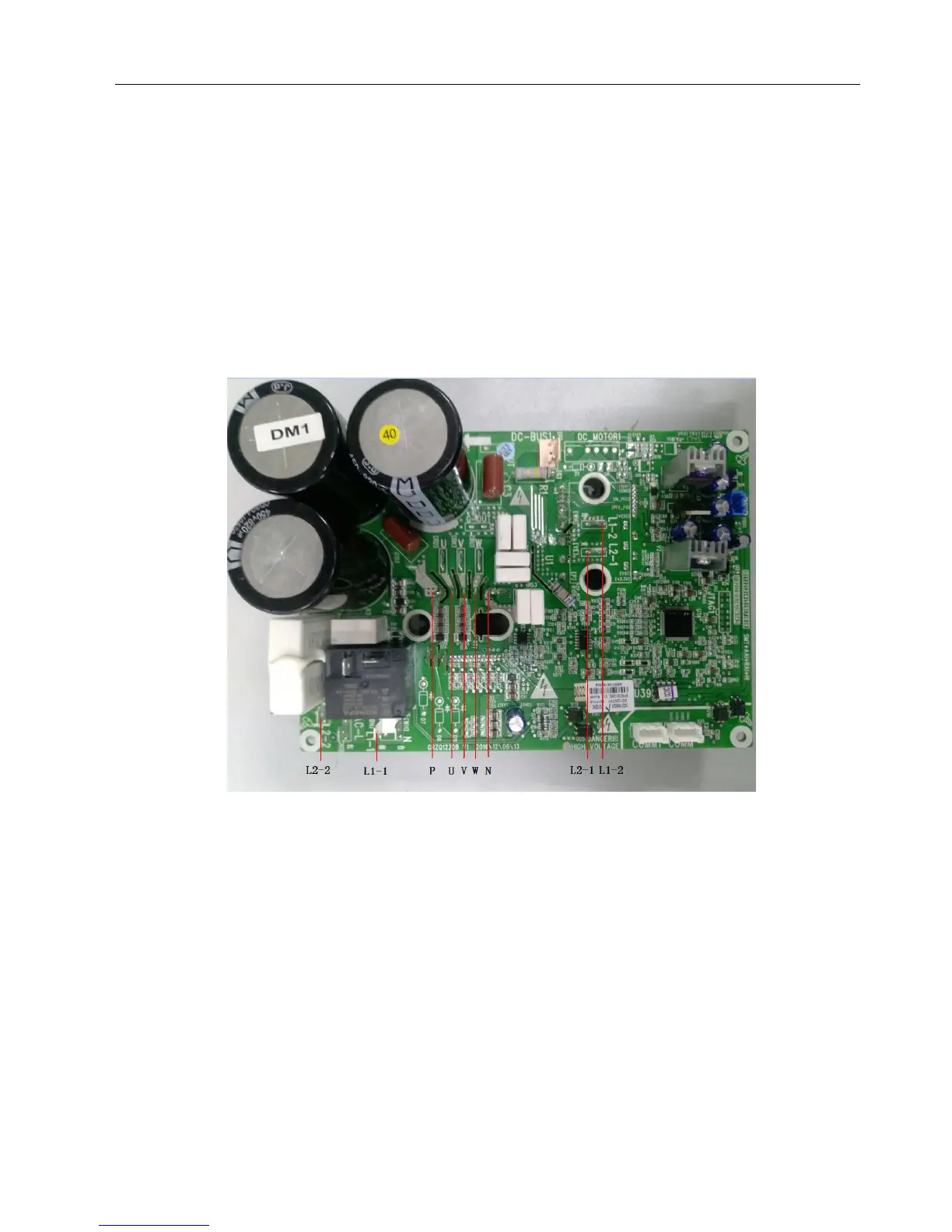
3.2.2.2 Method of Testing PFC Module Short Circuit: ( only for GUD100W/NhA-T, GUD125W/NhA-T,
GUD140W/NhA-T)
(1). Preparation before test: prepare a universal meter and turn to its diode option, and then remove the wires L1-2, L2-1 after it is
powered off for one minute.
(2). Testing Steps:
Step 1: put the black probe on the place P and the red one on the wiring terminal L1-2, L2-1respectively as shown in the
following figure to measure the voltage between L1-2P and.L2-1 P.
Step 2: put the red probe on the place N and the black one on the wiring terminal L1-2, L2-1respectively as shown in the
following figure to measure the voltage between N L1-2 and NL2-1.
(3). If the measured voltages between L1-2P ,L2-1 P, N L1-2 , NL2-1 are all among 0.3V-0.7V, then it indicates the PFC module is
normal; If any measured valve is 0, it indicates the PFC is damaged.
GUD100W/NhA-T

 Loading...