21
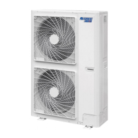
Condensing Unit
Service Manual
Table 6
Unit: mm
Model A B C D H
HNTF24/A-D
1220 225 1158 280 700
HNTF36/A-D
HNTF48/A-D
1420 245 1354 280 700
HNTF60/A-D
1.1.5 Installation Clearance Data
100cm or m ore
30cm or m ore
60cm or m ore
60cm or m ore
150cm or m ore
Figure 1-2-8
1.1.6 Drain Piping Work
(1). Installation of Drainage Pipeline
A Drainage outlet is located at both the left and right sides of the indoor unit. After selecting one Drainage
outlet, the other outlet shall be blocked by rubber plug. Bundle the blocked outlet with string to avoid
leakage, and also use thermal insulation materials to wrap the blocked outlet.
When shipped out from factory, both the Drainage outlets are blocked by rubber plugs.
When connecting the drainage pipe with the unit, do not apply excessive force to the pipeline at the side of
the unit. The xing position of the pipeline shall be near the unit.
Purchase general-purpose hard PVC pipe locally to be used as the drainage pipeline. When carrying
out connection, place the end of the PVC pipeline into the drainage hole. Use exible drainage tube and
tighten it with thread loop. Never use adhesive to connect the drainage hole and the exible drainage tube.
(As shown in Figure 1-2-9)
When the laid drainage pipe is used for multiple units, the common pipe shall be about 100mm lower than
the drainage outlet of each set of unit. A pipe with thicker wall shall be used for such purpose.
 Loading...