VRF Protocol Gateway
6
5.3 Button
SHT/DWN
When the fourth digit of DIP switch code is “1”, hold t
he button for 5s and
all indicators will be on. Reset the gateway controller.
Not use this button for this device temporarily.
5.4 DIP Switch
NOTICE!
Before using this device, please conduct DIP switch setting first, otherwise the
unit will not function normally!
Gateway dial-up setting area is consisting of function DIP switch code.
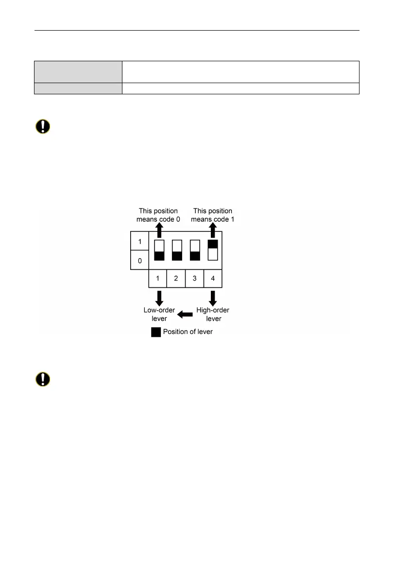
5.4.1 Diagram of Dial-up Machine
5.4.2 The 1st Lever of Functional DIP Switch—CAN2 Bus Matched
Resistance Setting
NOTICE!
Main control ODU or gateway at the top/end of CAN2 bus must be
with matched resistance; otherwise the communication might be wrong!
※
CAN2 bus: Specific meaning shall refer to the specification in Fig Internet
topological graph.
The No.1 dial-up button in function dial-up machine shall be used in the setting
in the matched resistance of CAN2 bus in this gateway.
When the gateway is at the top/end of CAN2 bus, the gateway shall be with the
matched resistance, then dial the No.1 function dial-up machine to 1.
When the gateway is not at the top/end of CAN2 bus, the gateway is not with
the matched resistance, then dial it to 0.
 Loading...


