VRF Protocol Gateway
5
5.2 LED Display
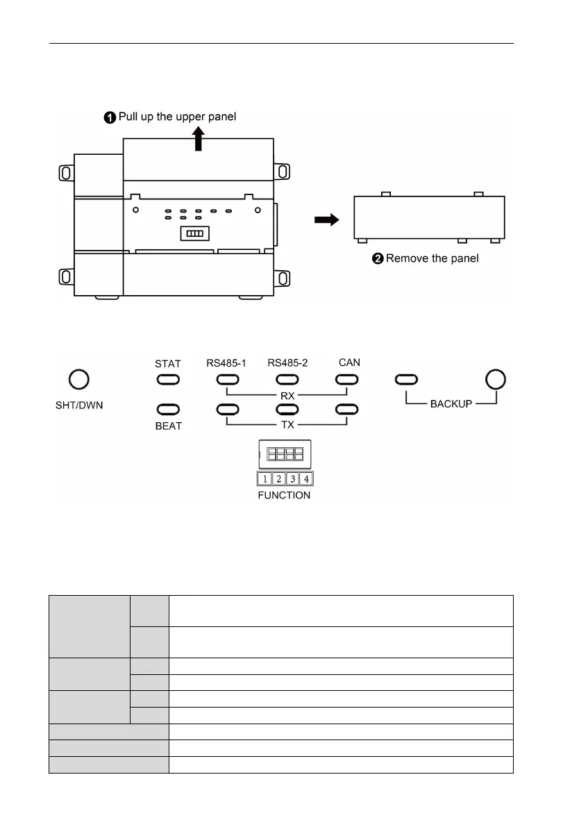
As shown in the picture below, open the black transparent front panel.
Fig 5.2 Schematic diagram of opening the black transparent board
Indicators, buttons and DIP switch are as shown below.
Fig 5.3 The schematic diagram of the gateway LED light board and DIP switch
The above LED indicator is mainly consist of two parts: status indicator (run,
power) and communication indicator (CAN and RS485). The following table is the
working status of each indicator.
CAN
RX
When receiving the data of equipment (eg. AC unit) which connects to
TX
When transmitting data to the equipment (eg. AC unit) which connects to
RS485-1
When the gateway receives data on the 485 bus, it blinks.
When the gateway sends data to the 485 bus, it blinks.
RS485-2
This device does not use this LED indicator.
This device does not use this LED indicator.
When power supply of Gateway is normal, it is on.
When Gateway is running normally, it blinks.
This device does not use this LED indicator.
 Loading...


