6
RS485 communication interface: It is connected to BMS through two-core
communication cable, to realize communication between Modbus Gateway(Mini)
and BMS or nearby Modbus Gateway(Mini).
5.2
LED Display
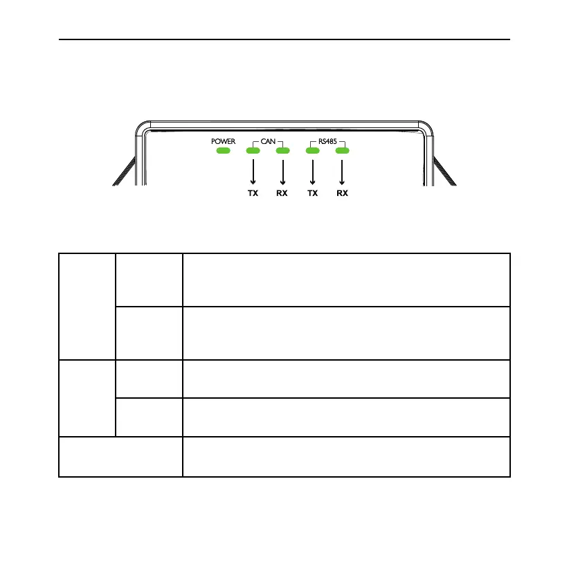
LED indicators shown in the above figure are divided into two parts: status
indicators (power) and communication indicators(CAN, RS485). Operation status
of each indicator is shown in the following table.
CAN
TX
When the data is transferred to the equipment (e.g. air
conditioner) connected with Modbus Gateway(Mini), it
will flash.
RX
When the data from the equipment (e.g. air conditioner)
connected with Modbus Gateway(Mini) is received, it will
flash.
RS485
TX
When the data is transferred to the Modbus bus, it will
flash.
RX
When the data from the Modbus bus is received, it will
flash.
Power
When power supply of Modbus Gateway(Mini) is normal,
it will be always on.
Modbus Gateway(Mini)