BACnet Gateway Kit for Central Air Conditioners
10
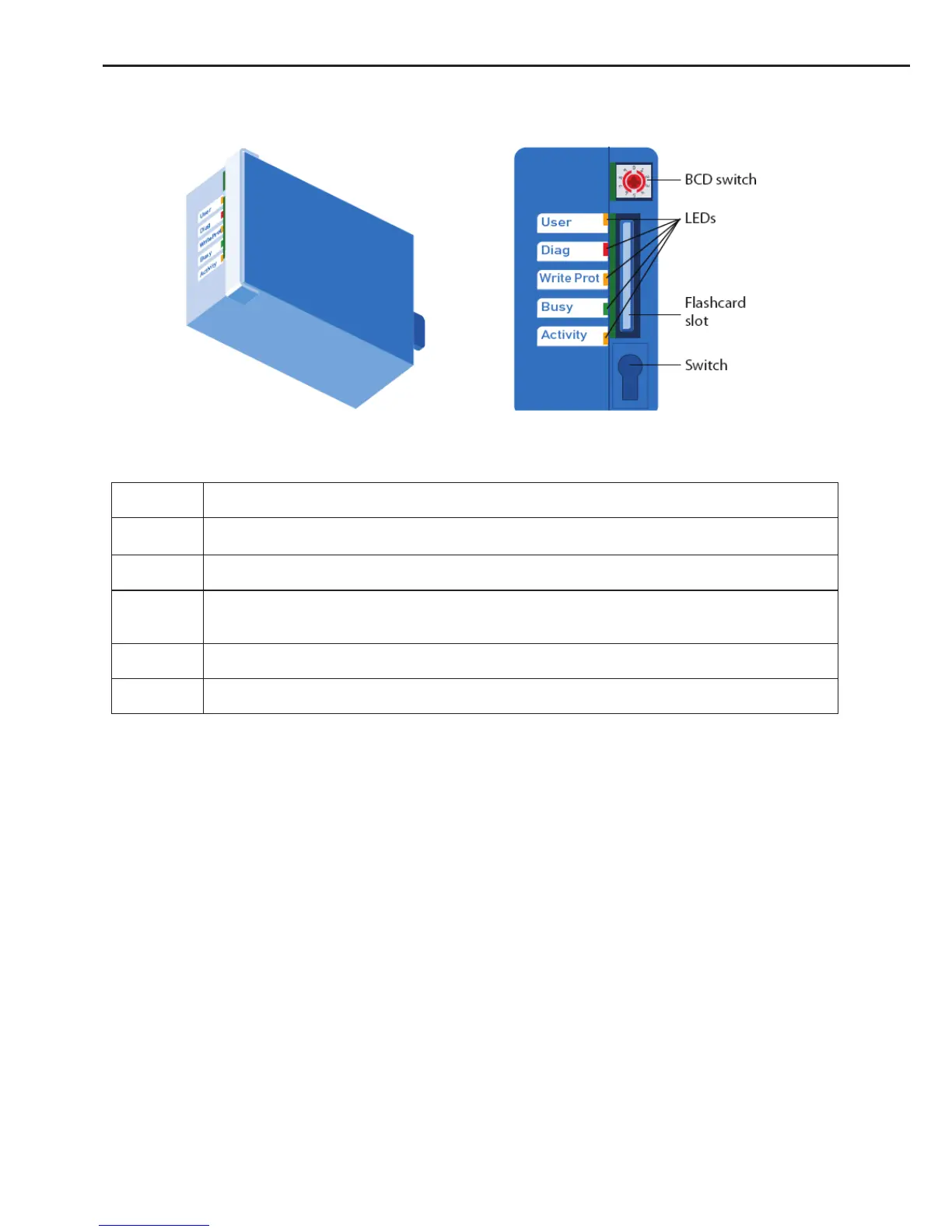
3.2.3 WEB Server Module Indicating LED
Fig.3-2 Wed Server Module PCD3.R600 Indicating LED
The memory module is tted with 5 LEDs:
LED Meaning
User
User LED, set by the user program with the base address of the module (SET = off; RES
= on)
Diag Flashes when there is an error message
Write Prot
Active when a "write-protected" condition is detected (read-only SD switch, BCD switch
or software)
Busy Do not remove the module when this LED is on.
Activity Works as with a hard disk drive; ashes when data being processed
Note:Do not remove the card when the "Busy" LED is on.
3�3 Installation Instructions
3.3.1 Side View of the Installation and Removal of the BACnet Gateway
The PCD3 CPUs and module holders can be snapped onto a 35 mm Top-hat rail according to
DIN EN60715 TH35 (formerly DIN EN50022).
Mounting the PCD3 on the top-hat rail
① .
Press bottom of housing onto the mounting surface
② .
Press upwards against the top-hat rail
③ .
Press top of housing against the mounting surface and snap into place
④ .
Push the housing down onto the top-hat rail to ensure that it is secure
Removal:
To remove the housing, push upwards and pull out.
 Loading...


