20
Fig. 21
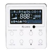
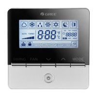
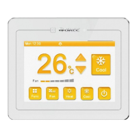
Wired Controller XE73-44/E
the rectangular hole behind the soleplate of the wired controller.
(3). Stick the soleplate of wired controller on the wall and then use screw M4×25 to fix
Table 3
the front panel and the soleplate of the wired controller together.
No. 1 2 3 4
Name of the Wired
Front Panel
Screw M4X25
Wired
Controller
embedded in the
wall
Socket box
1
Soleplate of the
4
Controller
3
5
2
installation hole, that is, no operation is allowed with electricity during the whole installation.
(2). Pull out the four-core twisted pair line from the installation holes and then let it go through
Note:
CN1 is 485 communication interface and it used Wired Controller XE73-44/E for connecting
the 4-core communication wire. These two needle stands(CN2、CN3) are used for connecting the
smart zone controller. There is no sequence for these two needle stands. You can connect one or
two needle stand(s) basing on the requirement.
Fig. 21 shows the installation steps of the wired controller, but there are some issues that
need
your attention.
(1). Prior to the installation, please firstly cut off the power supply of the wire buried in the
soleplate and installation hole on wall together.
(4). Insert the four-core twisted pair line into the slot of the wired controller and then
buckle