Multi-Blade Fire and Combination Fire Smoke Dampers 11
Actuator and Temperature Response Device Connections
Actuator Connections
Electrical and/or pneumatic connections to damper actuators should be made in accordance with wiring and piping
diagrams developed in compliance with applicable codes, ordinances and regulations (see Electrical Guidelines).
Temperature Response Device Connections
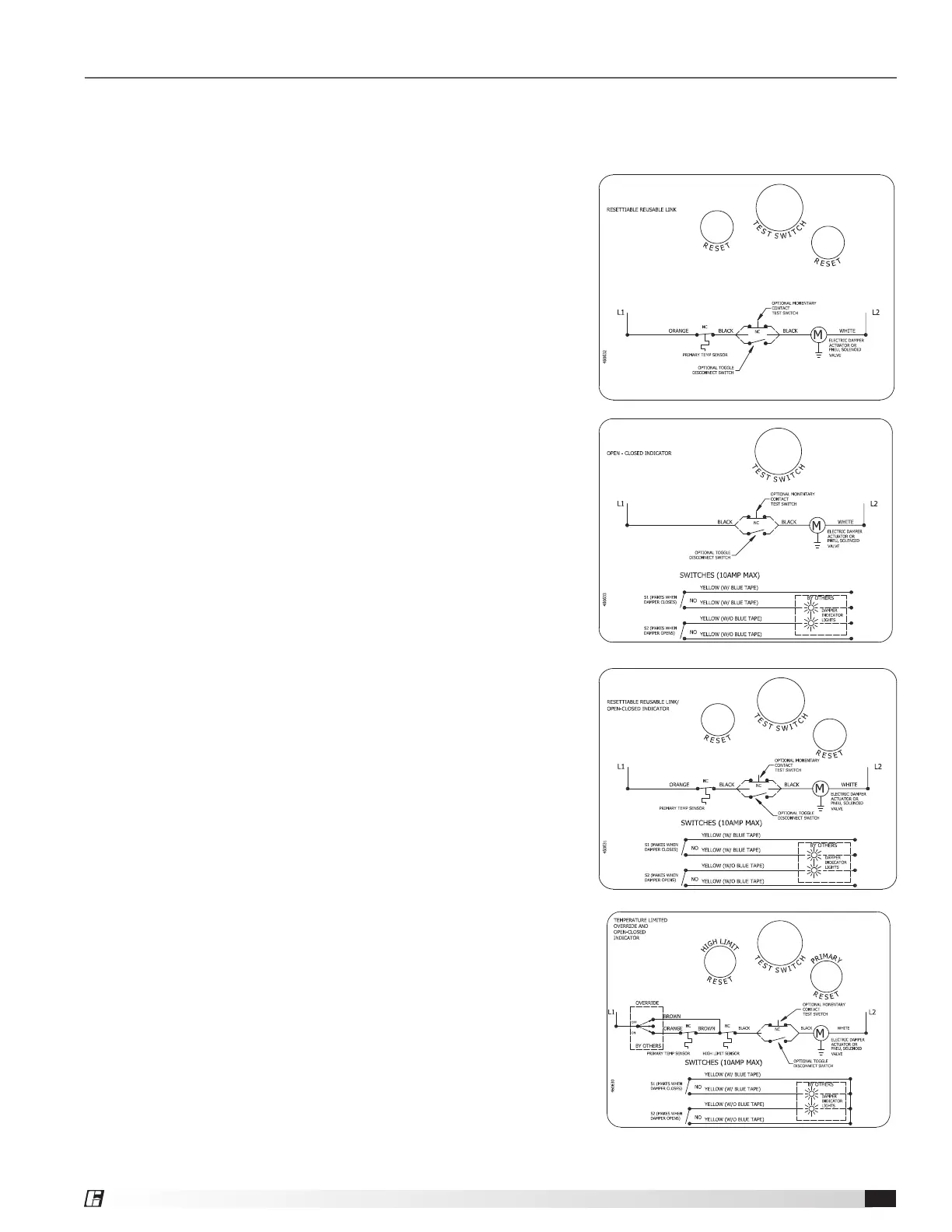
RRL: The RRL (resettable link device) incorporates a single
thermostat. When the thermostat temperature is
reached the sensor interrupts power to the actuator
and the actuator's spring return mechanism causes the
damper to close. Refer to Figure 25 for wiring of the
RRL thermostat.
OCI: The OCI (open or closed indicator) option contains
two single pole single throw switches used to indicate
the damper blade position. The switches provide a
positive open and closed signal and can be used in
conjunction with remote indicator lights. Refer to
Figure 25 for wiring of the OCI option.
RRL/OCI: The RRL/OCI performs the function of an RRL
and OCI (see description above). Refer to Figure
26 for wiring of the RRL/OCI option.
TOR: The TOR (temperature override device) option
incorporates two thermostats with fixed settings
(usually 165°F [74°C] and 350°F [177°C]). The primary
sensor (the sensor with the lower temperature setting)
can be bypassed by an external contact closure
allowing the damper to reopen until the secondary
temperature is reached (the sensor with the higher
temperature setting). See Figure 27.
The TOR assembly contains two single pole single
throw switches used to indicate damper blade
position. The switches provide a positive open and
closed signal and can be used in conjunction with
remote indicator lights. See Figure 27 for wiring of
the TOR thermostats and indicator switches.
If either the TOR or the RRL is ordered with a
pneumatic actuator, an EP switch is required
with an appropriate electric power circuit to allow
the electric thermostat to control the pneumatic
actuator.
Ratings (Figure 25, 26, 27, & 28)
Integral Switch Type: Single Pole, double throw
Electrical Capacity: 10 Amps, 1/3 hp, 120 or 240 Vac
½ Amp, 125 Vdc;
¼ Amp 250 Vdc
5 Amps, 120 Vac “L” (lamp load)
1.0 Amps, 24 Vac
1.5 Amps, 24 Vdc
Temperature Limit: 165° F (standard primary sensor)
212° F (optional primary sensor)
250° F (secondary sensor )*
350º F (secondary sensor)*
* based on actuator temperature rating
Figure 26: OCI
Figure 27: RRL/OCI
Figure 28: TOR
Figure 25: RRL Wiring
 Loading...


