Multi-Blade Fire and Combination Fire Smoke Dampers6
Inserting Damper into Wall/Floor Openings
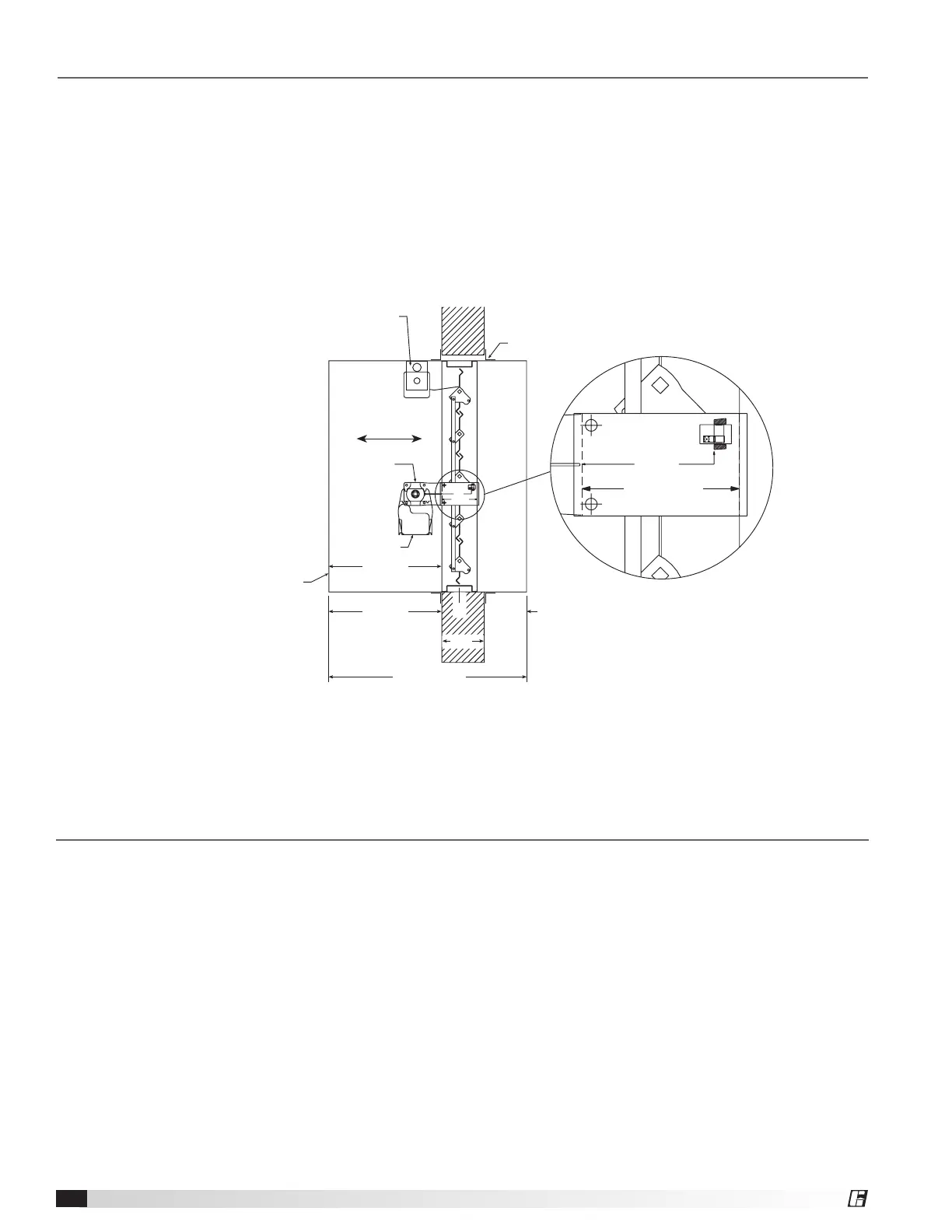
Insert the sleeved damper assembly into the prepared opening. Refer to label on outside of sleeve for the
recommended location of the damper in the wall or floor (see Dimension A and Detail 1, Figure 8).
Special attention must be paid to ensure the following:
1) The C
L
(centerline) of the damper frame remains within the plane of the wall or floor
2) Attachments made through the retaining angle do not penetrate the ‘No Screw’ area designated on the
damper sleeve.
3) The sleeve does not extend more than 16 in. (406 mm) beyond the wall or floor on the actuator side of the
damper and 6 in. (152 mm) on the side opposite the actuator. The sleeve may also extend up to 16 in. (406
mm) beyond the wall or floor if the damper has a factory supplied access door.
Optional blade indicator
and/or electric link.
LINE OF WALL
DO NOT INSTALL SCREWS
BETWEEN THESE LINES
AROUND ENTIRE DAMPER
Retaining Angles
(see Section 4)
Line of Wall
Airflow
Detail 1
DO NOT INSTALL SCREWS
BETWEEN THESE LINES
AROUND ENTIRE DAMPER
Access door required on
jackshaft side of damper.
Refer to the latest edition
of NFPA 90A.
Jackshaft
Actuator
Damper
Sleeve
Sleeve Length (L)
6 in. max.
16 in. max.
‘A’ Dim.
(Distance from
end of sleeve to
face of damper)
458549
T
w
C
L
Figure 8: Properly installed combination fire smoke damper
Most fire and combination fire smoke dampers come with factory supplied sleeves. For field supplied sleeves, see
the Field Supplied Sleeves supplement at www.greenheck.com.
Securing the Damper/Sleeve Assembly to Wall/Floor Openings
All fire and combination fire smoke dampers may utilize the two sided angle installation method described below.
1
1
⁄2 hour rated fire and combination fire smoke dampers may use the single sided angle installation method up to the
following maximum sizes:
• Vertical mount: 80 in. W x 50. in. H (2032 mm W x 1270 mm H), 50 in. W x 80 in. H
(1270 mm W x 2032 mm H), or 40 in. W x 100 in. H (1016 mm W x 2540 mm).
• Horizontal mount: 144 in. W x 96 in. H (3658 mm W x 2438 mm H)
Retaining Angle Gauge: Retaining angles for 1½ hour rated dampers with a width and height 48 in. (1219 mm) or
less must be a minimum of 20 ga. (1 mm). Retaining angles for all 3 hour rated dampers and all dampers with a width
or height greater than 48 in. (1219 mm) must be a minimum of 16 ga. (1.5 mm).
Retaining Angle Size: The leg of the retaining angle on the damper sleeve shall be a minimum of 1¼ in. (32 mm).
The leg of the retaining angle on the wall/floor shall be long enough to cover the annular space and overlap the wall/
floor by a minimum of 1 in. (25 mm).
 Loading...


