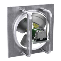
Sidewall Propeller Fans 3
• Check chart below for correct wall opening
dimensions.
• Check motor voltage and amperage rating for
compatibility with electrical supply. Supply wiring
must be properly fused and conform to local and
national codes.
• Motor load amperage must be checked and
compared to nameplate rating to avoid serious
damage to motor when speed is increased.
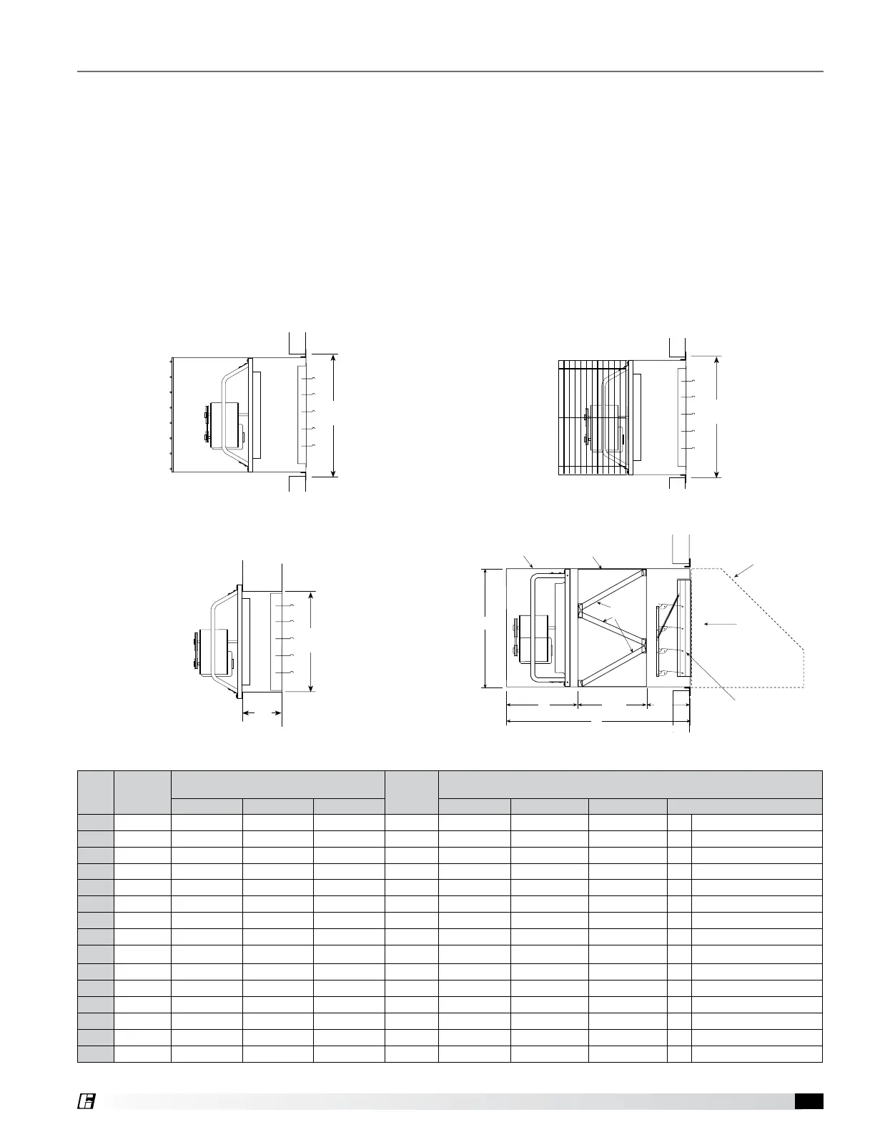
Wall Opening Requirements
Wall opening size and propeller-to-damper distance
are two important dimensions for fan installation. Fans
mounted to the wall require a different wall opening
(W.O.) size than those mounted in collars or wall
housings. Propeller-to-damper distance (M) is important
to reduce turbulence and damper flutter which may lead
to premature damper failure.
Figure 1 and 2 show the wall opening (W.O.) required
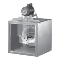
for installations with either a wall housing or collar.
Figure 3 shows the recommended wall opening (W.O.)
and the minimum distance (M) suggested between the
fan and damper for direct to wall installations.
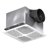
Figure 4 shows the dimensions and wall opening
(W.O.) required for installations with a filtered supply
wall housing.
Pre-Installation Checks
Fan
Size
Damper
Size
Square
Recommended Wall Opening (W.O.)
Square
M
Minimum
Filtered Supply Wall Housing Only
Figures 1 & 2 Figure 3 Figure 4 A B C Filter Quantity & Size
8
10 (254) 14-1/4 (362) 10-1/2 (267) - 6 (152) - - - - -
10
12 (305) 16-1/4 (413) 12-1/2 (318) - 6 (152) - - - - -
12
14 (356) 19-1/4 (489) 14-1/2 (368) - 7 (178) - - - - -
14
16 (406) 21-1/4 (540) 16-1/2 (419) - 8 (203) - - - - -
16
18 (457) 23-1/4 (591) 18-1/2 (470) - 9 (229) - - - - -
18
20 (508) 25-1/4 (641) 20-1/2 (521) - 10 (254) - - - - -
20
22 (559) 27-1/4 (692) 22-1/2 (572) - 12 (305) - - - - -
24
26 (660) 33-3/4 (857) 26-1/2 (673) 33-3/4 (857) 13 (330) 32-1/4 (819) 63 (1600) 24 (610) 4 23-1/4 x 16-1/4 (591 x 413)
30
32 (813) 39-3/4 (1010) 32-1/2 (826) 39-3/4 (1010) 13 (330) 38-1/4 (972) 65 (1651) 26 (660) 4 24-5/8 x 19-1/4 (625 x 489)
36
38 (965) 45-3/4 (1162) 38-1/2 (978) 45-3/4 (1162) 14 (356) 44-1/4 (1124) 67-1/4 (1708) 28-1/4 (718) 6 23-1/4 x 22-1/8 (591 x 562)
42
44 (1118) 51-3/4 (1314) 44-1/2 (1130) 51-3/4 (1314) 15 (381) 50-1/8 (1273) 72-7/8 (1851) 34 (864) 6 24-1/8 x 25 -1/8 (613 x 638)
48
50 (1270) 57-3/4 (1467) 50-1/2 (1283) 57-3/4 (1467) 16 (406) 56-1/8 (1426) 72-7/8 (1851) 34 (864) 12 23-1/4 x 18-3/4 (591 x 476)
54
56 (1422) 63-3/4 (1619) 56-1/2 (1435) 63-3/4 (1619) 17 (432)
62-3/8 (1584)
79-11/16 (2024) 40-11/16 (1033) 12 23-1/4 x 20-3/4 (591 x 527)
60
62 (1575) 69-3/4 (1772) 62-1/2 (1588) - 19 (483) - - - - -
72
74 (1880) 84-3/4 (2153) 74-1/2 (1892) - 19 (483) - - - - -
All dimensions given in inches (millimeters). Filters are 2 inch (51 mm) nominal thickness. Above filter sizes are actual dimensions.
Figure 3 - Direct to Wall Installation
Figure 1 - Wall Housing Installation Figure 2 - Wall Collar Installation
Figure 4 - Filtered Supply Wall Housing Installation
W.O.
M
W.O.
W.O.
Filters
Wall
Housing
Filter
Section
INTERIOR
Wall
EXTERIOR
Optional 90º
Weatherhood
Filters
Airflow
Optional
Damper
Wall
A
C
B
24 in. 15 in.