Greenlee Textron / Subsidiary of Textron Inc.
14
4455 Boeing Dr., Rockford, IL 61109-2988 815/397-7070
1399 and 1399-22 Band Saws
Wiring Diagrams
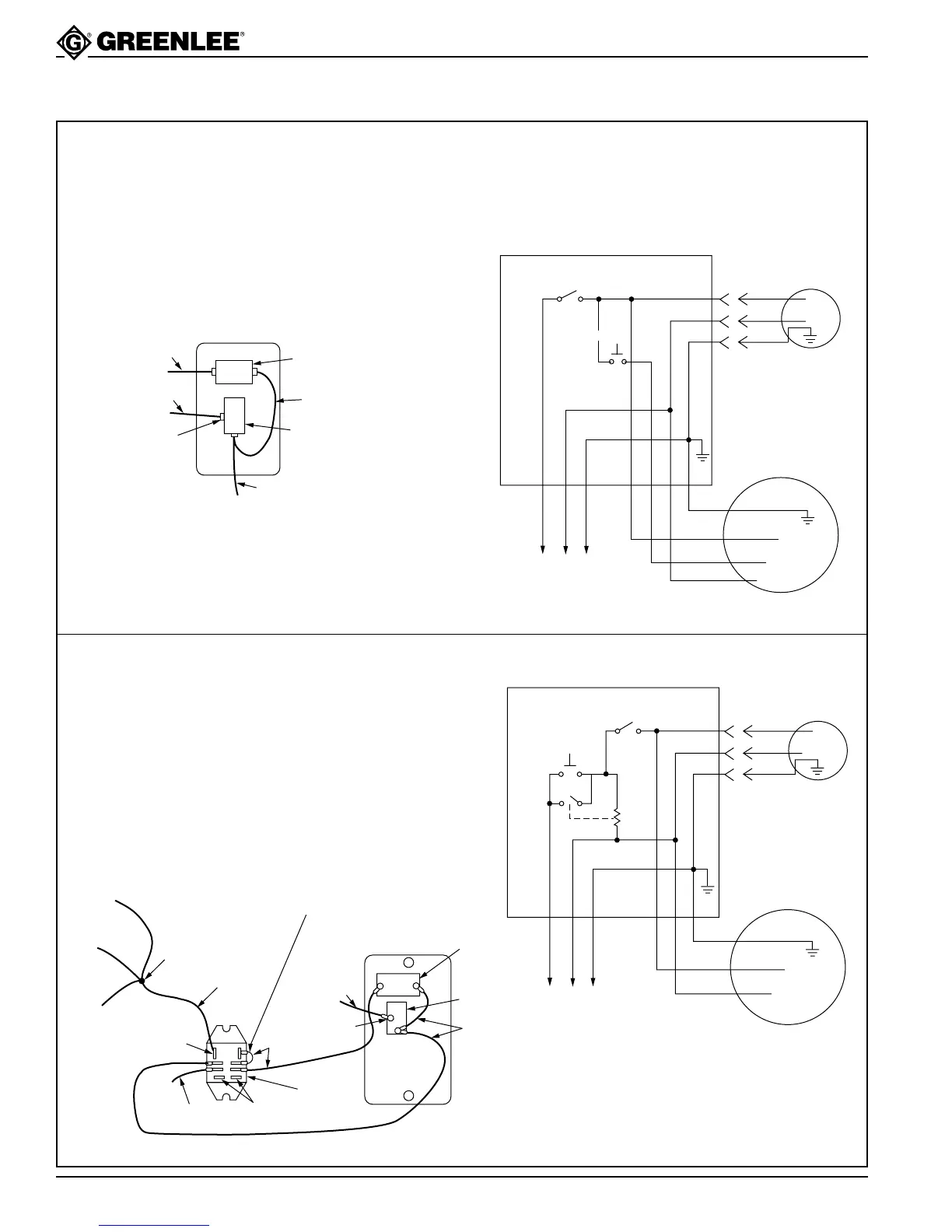
For 115-volt models preceding serial number 3500420:
1. Connect the white wire from the cord set to the white
wires from the power cord and motor cord.
2. Connect the black wire to the ON/OFF toggle switch
terminal “E”.
3. Connect the green wire to the grounding screw in the
back of the switch box.
Note: When replacing the motor (part no. 503 2153.6)
on a 115-volt unit with a serial number preceding
3500420, also install and connect a relay (part no.
918 6348.1) as shown.
BLACK WIRE TO
POWER CORD
ON/OFF
TOGGLE
SWITCH
BLACK
JUMPER
WIRE
RESET
BUTTON
BACK SIDE OF
SWITCH BOX COVER
RED WIRE
TO MOTOR
BLACK WIRE
FROM MOTOR
“E”
TERMINAL
SCHEMATIC
(ON/OFF)
BLACK
OPTIONAL
COOLANT
PUMP
MOTOR
4
2
1
115 VOLT
SUPPLY
BLACK
BLACK
WHITE
WHITE
GREEN
GREEN
RED
WHITE
GREEN
(START)
For 115-volt models beginning with serial number
3500420:
1. Connect the white wires from the cord set, motor, and
coolant pump (optional) to relay coil terminal “F”.
2. Connect the black wire from the motor to the
ON/OFF toggle switch terminal “E”.
3. Connect the green wire from the motor to the grounding
screw in the back of the switch box.
SCHEMATIC
(ON/OFF)
(RESET)
BLACK
BLACK
OPTIONAL
COOLANT
PUMP
MOTOR
115 VOLT
SUPPLY
BLACK
WHITE
GREEN
WHITE
WHITE
GREEN
GREEN
(RELAY)
BLACK
JUMPER
WIRES
RESET
BUTTON
TOGGLE
SWITCH
BACK SIDE OF
SWITCH COVER
(F) COIL
TERMINAL
BLACK WIRE TO
POWER CORD
NOT USED
RELAY
RED
WIRES
THIS JUMPER
WIRE IS NEEDED
IF TERMINALS ARE
SOLDERED TOGETHER
WHITE WIRE
FROM MOTOR
WHITE
JUMPER
WIRE
WIRE
NUT
WHITE WIRE
FROM POWER
CORD
WHITE WIRE
FROM OPTIONAL
COOLANT PUMP
BLACK WIRE
FROM MOTOR
“E”
TERMINAL