Greenlee Textron / Subsidiary of Textron Inc.
29
4455 Boeing Dr., Rockford, IL 61109-2988 815/397-7070
1399 and 1399-22 Band Saws
Appendix C - Wet Cutting System
Assembly
Assembly of the Wet Cutting System will require the
following:
• hammer • .104 dia. (#37) drill bit
• slotted screwdriver • .159 dia. (#21) drill bit
• ruler • .201 dia. (#7) drill bit
• adjustable wrench • .375 dia. (3/8") drill bit
• portable electric drill • 1/4 - 20 UNC tap
• #10 - 32 UNF tap
1. Install the cord and strain relief:
a. Disconnect the saw from the power supply.
b. See the Exploded View—Switch and Dash Pot
Details. Remove the switch box cover. Remove
the knock-out from the bottom of the switch box.
c. See Wiring Diagrams. Install the strain relief and
cord set.
Note: On 220-volt models, install the cord from
the transformer.
d. Replace the switch box cover.
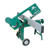
Figure 1
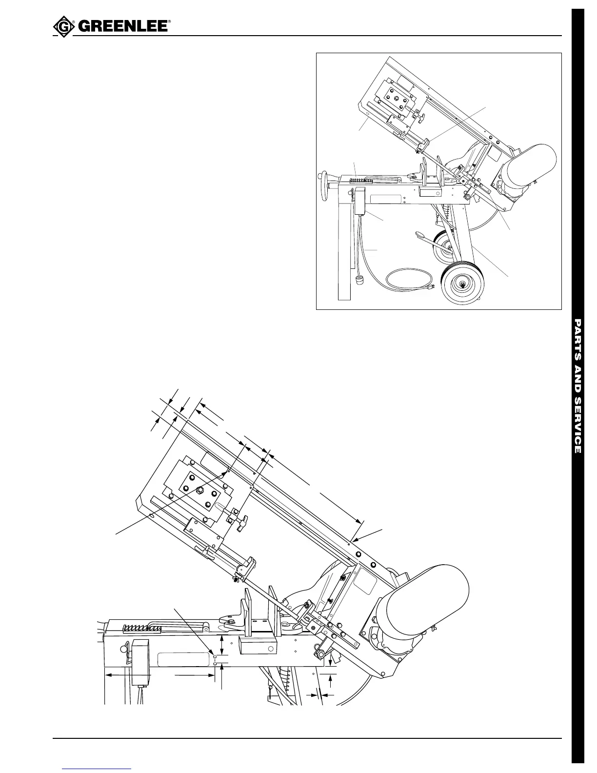
Figure 2
BLADE
ROLLER
SUPPORT
HEAD FRAME
SAW BED
SWITCH
BOX
DRIVE END
GUIDE
BRACKET
REAR LEG
CORD SET
2. See Figures 2 & 3. Locate and drill:
a. Three .201 dia. (#7) holes (labeled “A”).
Thread these holes with the 1/4 - 20 UNC tap.
b. Two .104 dia. (#37) holes (labeled “B”).
c. Two .159 dia. (#21) holes in the blade roller
support. Thread these holes with the #10 - 32
UNF tap.
d. On units preceding serial no. VY - 3500357:
drill four .375 (3/8") holes in the saw bed (two
on each side).
DRILL .201 DIA. (#7) HOLE &
TAP 1/4" - 20 UNC THREAD
(3) HOLES MARKED “A”
DRILL .104 DIA. (#37) HOLE
(2) HOLES MARKED “B”
3/4"
2-3/4"
A
A
B
B
DRILL 3/8" DIA. HOLE
(4) HOLES, (2) BOTH SIDES
11-1/4"
8"
16"
3-5/8"
15-1/4"
1-1/2"
1-1/2"
A
3"
1"