Greenlee Textron / Subsidiary of Textron Inc.
30
4455 Boeing Dr., Rockford, IL 61109-2988 815/397-7070
1399 and 1399-22 Band Saws
Wet Cutting System (cont’d)
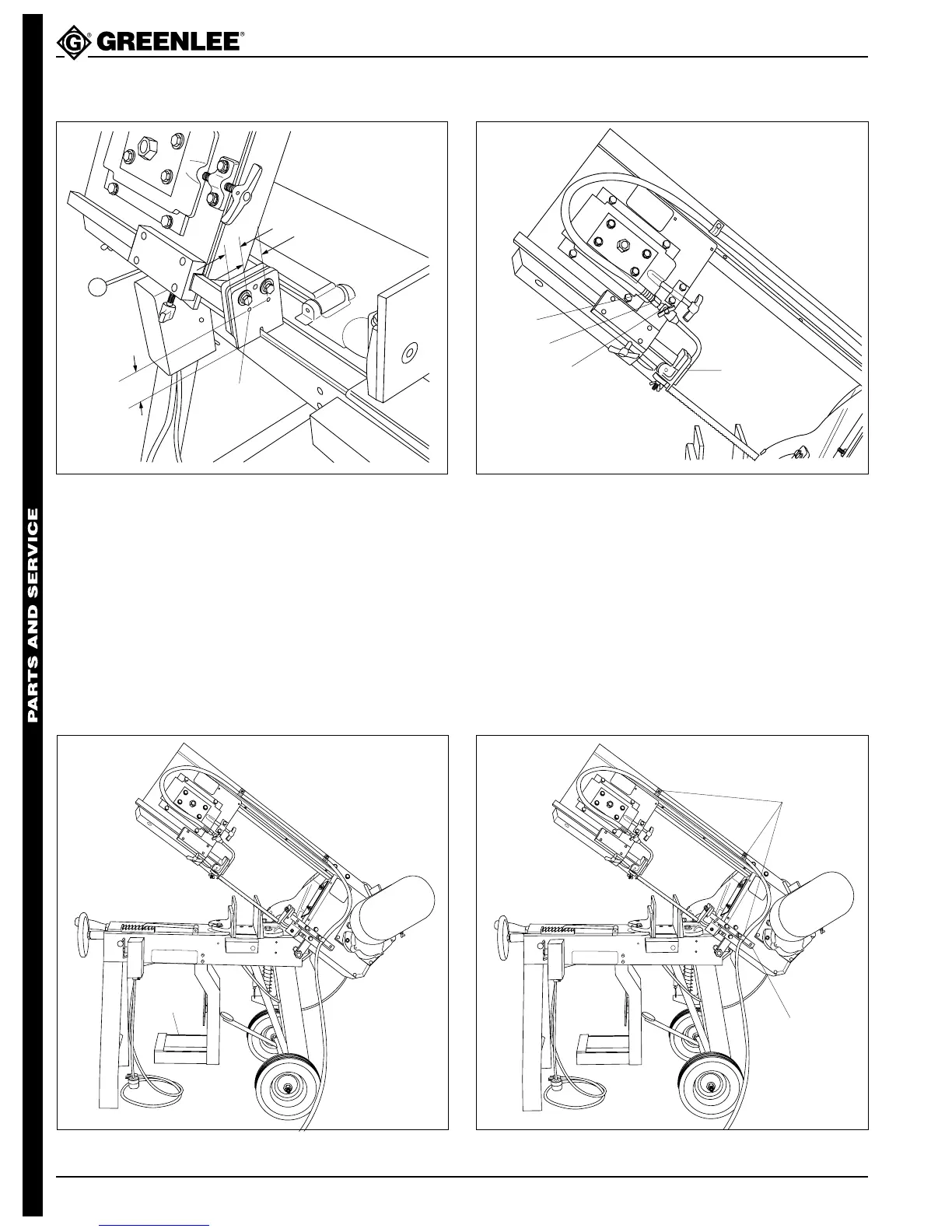
Figure 6Figure 5
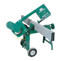
Figure 4
Figure 3
1-3/4"
13/16"
1-1/16"
DRILL
.159 DIA. (#21) HOLE &
TAP #10-32 UNF THREAD
(2) HOLES AS SHOWN
HOSE CLAMP
ADAPTER
NEEDLE VALVE
COOLANT
NOZZLE
HOSE
STRAPS
DRIVE END
GUIDE
BRACKET
4. See Figure 5. Assemble the coolant nozzle, needle
valve, and adapter. Attach coolant hose to the
adapter and secure the hose with the hose clamp.
5. See Figure 6. Attach the coolant nozzle to the blade
roller support with two #10 - 32 x 3/8 round head
machine screws (14). Secure the coolant hose with
three hose straps. Attach two of the hose straps
with two 1/4 - 20 x 1/2 round head machine screws
(13); attach the third hose strap screw on the drive
and guide bracket, as shown.
3. See Figure 4. Attach the mounting bracket to the
saw bed with four 5/16 - 18 x 3/4 hex head cap
screws (20) and lockwashers (21). Use the mount-
ing holes made in Step 4d.
Note: See the Exploded View: on 220-volt models,
assemble the transformer and mounting bracket to
the coolant tank mounting bracket prior to attaching
to the saw bed.
MOUNTING
BRACKET