Greenlee Textron Inc. / Subsidiary of Textron Inc.
8
4455 Boeing Dr., Rockford, IL 61109-2988 815/397-7070
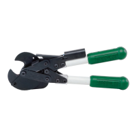
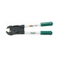
764 Ratchet Cable Cutter
Disassembly
This tool consists of three basic operating mechanisms
(see Figure 1).
1. Cutter jaw mechanism: stationary jaw (1), movable
jaw (3), jaw bolt (25), jaw spacer (4), return spring
(5), and related hardware.
2. Jaw drive mechanism: master drive gear (16),
master gear shaft (26), drive pawl (15), pawl spring
(12), pawl shaft (19), top and bottom handle plates
(14 and 22) and operating lever.
3.
Jaw holding mechanism: holding pawl (15), pawl
spring (17), pawl shaft (19) and pawl release pin (27).
Maintenance (cont’d)
The jaw mechanism can be removed without removing
the boot. Both the jaw mechanism and drive mechanism
can be removed and serviced without disassembly of
the housing.
1. Turn back boot (33) and remove cap screw (21).
Release tension on extension spring (5) by opening
the operating lever and rotating release pin (27)
outward.
2. Turn back boot and remove nut (6).
3. Remove bolt (25) and spacer (4).
4. Disconnect spring (5) from housing (13).
5.
Unbutton one side of button strip (34) and spread
the sides of the boot to clear the pawl release pin
(27). Push the boot forward (away from the handles).
Tip the boot as needed to disengage the boot from
the notches at the top and bottom of the housing.
Alternately move the boot forward at the top and
bottom until the boot can be rotated off the tool.
6. Remove retaining ring (9) from gear shaft (26).
Also remove two screws (8) from stop pin (20).
7. Remove shaft (26) and gear (16).
8. Remove the operating lever assembly.
9. Remove rubber bumpers (10) from release pin (27).
10. Remove two housing screws (11). Lift housing from
tool.
11. Remove two screws (11) to disassemble operating
lever assembly and remove pawl (15), pawl spring
(12) and pawl shaft (19).