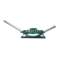
777 Segment Bender
Greenlee Textron Inc. / Subsidiary of Textron Inc. 4455 Boeing Dr., Rockford, IL 61109 815-397-7070
5
Bending Conduit
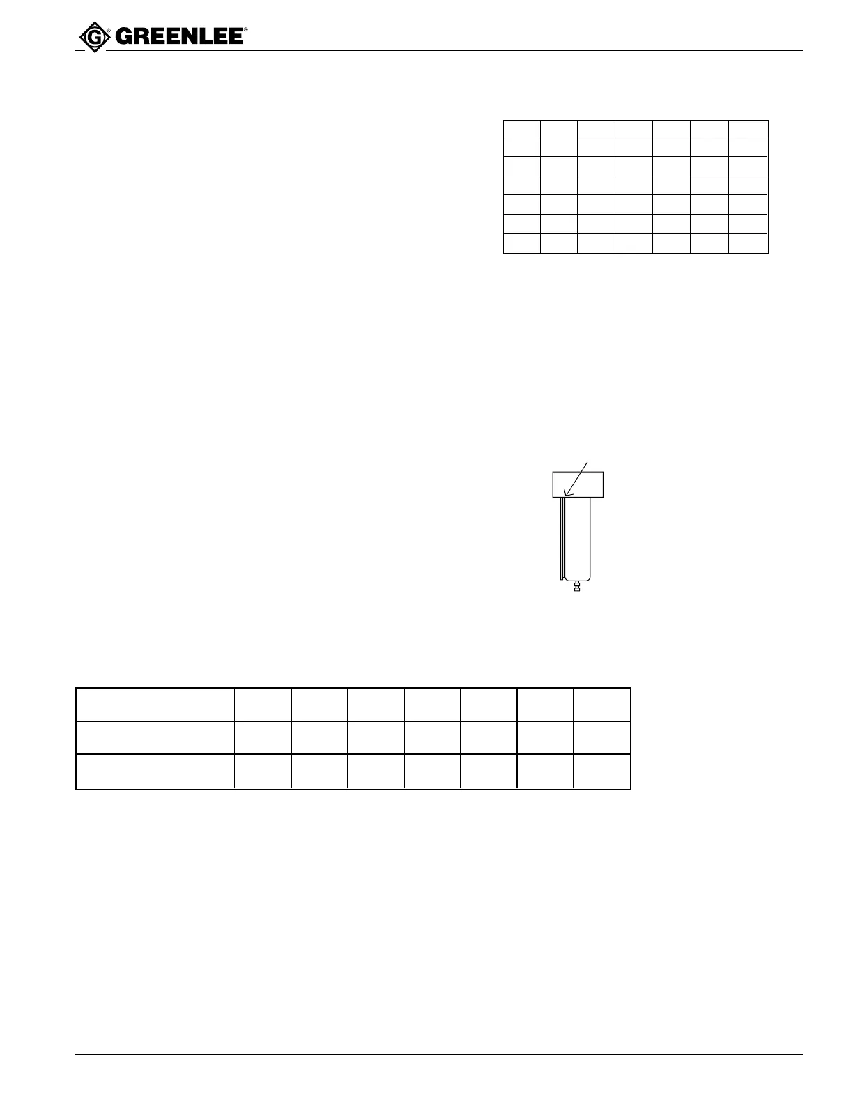
1. Loosen the ram travel scale nut; set the ram travel
scale, which is read at the edge of the block, to zero.
Tighten the nut.
2. Mark the conduit. See the instructions for marking the
conduit for the necessary bend in this manual.
3. Insert the conduit into the bender. Align the bending
mark on the conduit with the center of the bending
shoe.
4. Consult the Ram Travel Table to find the amount of
ram travel necessary to accomplish the bend.
5. Use the hydraulic pump to advance the ram by the
amount of ram travel found in Step 4.
6. Release the hydraulic pressure at the pump and
move the conduit to the next bending position.
Note: If making an offset bend, rotate the conduit 180˚
before making the second bend. If making a
three-bend saddle, rotate the conduit 180˚ before
making the second and third bends. If making a
four-bend saddle, rotate the conduit 180˚ before
making the second and fourth bends.
7. Repeat Steps 5 and 6 until the last bend is made.
8. Remove the conduit from the bender.
Note: To use this table, find the size of the conduit
to be bent in the leftmost column and find the
desired angle of bend in the top row. The
intersection of the appropriate column and row
shows the approximate amount of ram travel
necessary to accomplish the desired angle of
bend.
10˚ 15˚ 30˚ 45˚ 60˚ 90˚
1/2 1-5/8 1-7/8 2-3/4 3-1/2 4-3/8 5-7/8
3/4 1-3/8 1-5/8 2-1/2 3-1/4 4 5-1/2
1 1-1/2 1-7/8 2-13/16 3-3/4 4-1/2 6-1/4
1-1/4 1-7/8 2-1/4 3-1/4 4-1/4 5-1/4 7
1-1/2 1-1/4 1-5/8 2-5/8 3-5/8 4-7/16 5-15/16
2 1-1/4 1-11/16 2-7/8 3-15/16 5 6-5/8
Conduit
Size
FIGURES ARE APPROXIMATE
Angle of Bend
RAM TRAVEL SCALE
READ SCALE AT EDGE OF BLOCK
Ram Travel Table for Common Bends
1-1/4 1-1/2 2 2-1/2 3 3-1/2 4
7-1/4 8-1/4 9-1/2 11-7/16 13-3/4 16 18-1/4
184.1 209.5 241.3 290.5 349.2 406.4 463.5
Rigid Shoe Size
(inches)
Bending Radius
(inches)
Bending Radius
(mm)
Centerline Bending Radii for the 777 Bender
 Loading...