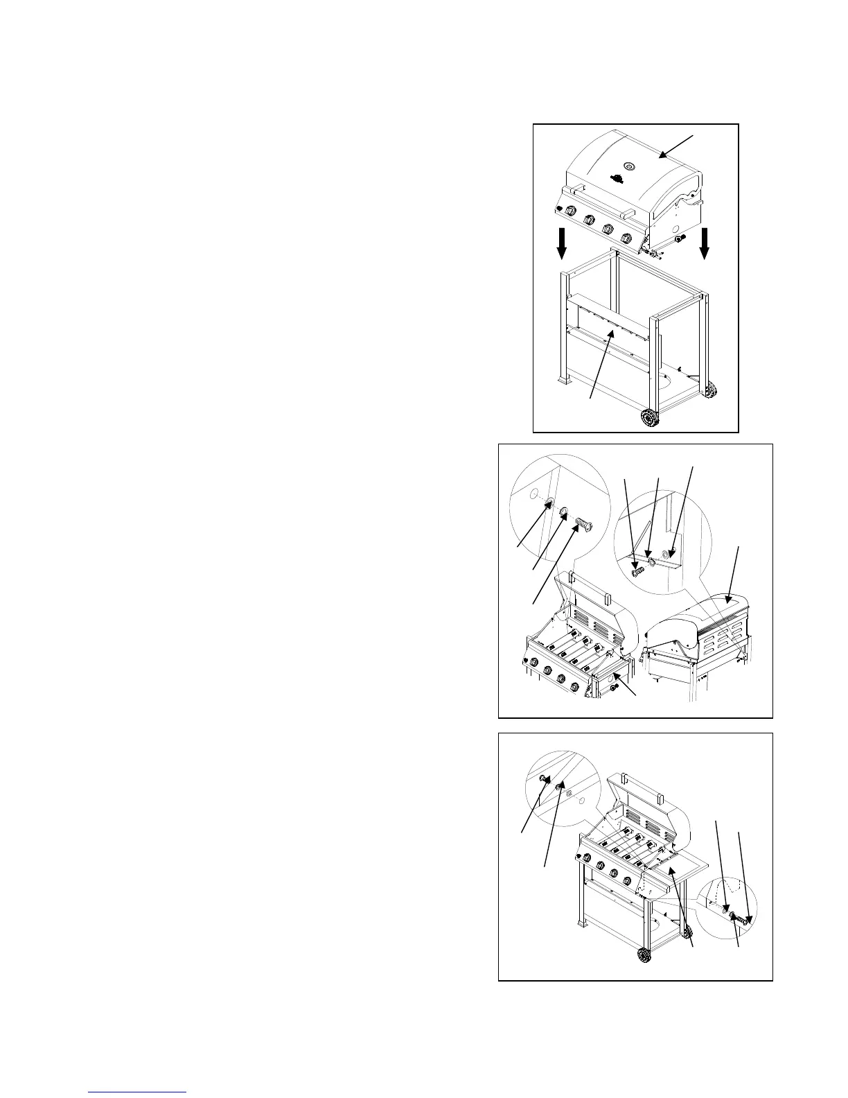
10. Firebox Assembly
a) Remove the Firebox Assembly (A)
from the carton and carefully place
onto the grill cart. Lid handle will face
front and be above Condiment Tray (T).
As shown in Fig.12.
NOTE: We suggest two persons lift
the firebox when assembling. Be sure
the hose and regulator are place inside
the cart when placing Firebox (A). Be
sure to remove all packaging material
during assembly.
.
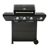
b) Lift the lid and from inside the Firebox Assembly (A)
attach the Cart Frame (H) using four ¼-in. x 15-mm Truss
Head Screws (CC), four ¼-in. Locking Washers (DD), and
four ¼-in. Flat Washers (KK). As shown in Fig. 13.
c) From the left and right sides of the Firebox Assembly (A)
exterior secure the Firebox Assembly (A) to the rear leg
with two 5/32-in. x 10-mm Truss Head Screws (AA),
two 5/32-in. Locking Washers (BB), and two ¼-in.
Flat Washers (KK). As shown in Fig. 13.
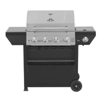
11. Side Burner Shelf Assembly
a) Align the holes on Side Burner Shelf (D)
with the holes located on the side of the
firebox. Attach from inside the firebox by
using three 1/4-in. x 15-mm Truss Head
Screws (CC) and three 1/4-in. Locking
Washers (DD) and three ¼-in. Flat Washer (KK).
b)Secure side burner shelf and firebox
control panels with one 5/32-in. x 10-mm
Truss Head Screw (AA) and one 5/32-in Locking Washer (BB)
and one ¼-in. Flat Washer (KK). As shown in Fig. 14.
Fig. 14
Fig. 12