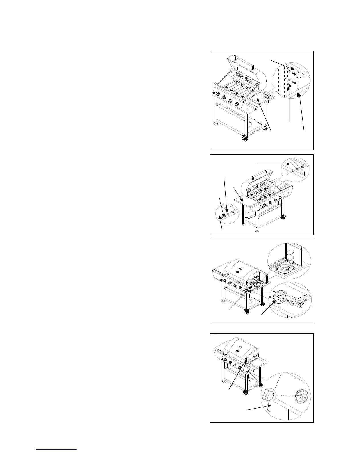
c)Use four 5/32-in. x 10-mm Truss Head Screw (AA)
and four 5/32-in Locking Washer (BB)
to assemble the Triangle Bracket,
Right (P) to the bottom rear of Side
Burner Shelf (D) and Cart Leg, Back Right (J).
As shown in Fig. 15.
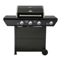
12. Left Side Shelf Assembly
Repeat Step 11 to assemble Left
Side Shelf (E) and Triangle
Bracket, Left (O).as shown in Fig.16.
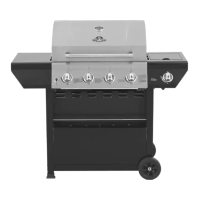
13. Side Burner Valve Installation
a) Remove the two 4mm screws with
locking washers that are pre-attached
to the valve. Then place the Bezel (L)
on the Side Burner Shelf (D) control
panel. From underneath, insert
the side burner valve into the Side
Burner Shelf (D) control panel and Bezel (L).
Align the holes in the Bezel (L) with holes in
the valve and attach with two 4mm screws.
The two screws hold the bezel, control panel,
and valve together. As shown in Fig. 17.
b) Insert Side Burner Control Knob (M) onto
the valve stem and tighten it by using the
Allen Key (FF). As shown in Fig. 18.
Note: Insert the allen Key into the hole prior to
placing the knob on the valve stem. Place the knob on
the valve stem and tighten.
Fig. 15