-2-
Model G0962 (Mfd. Since 02/24)
To reduce your risk of
serious injury, read this
entire manual BEFORE
using machine.
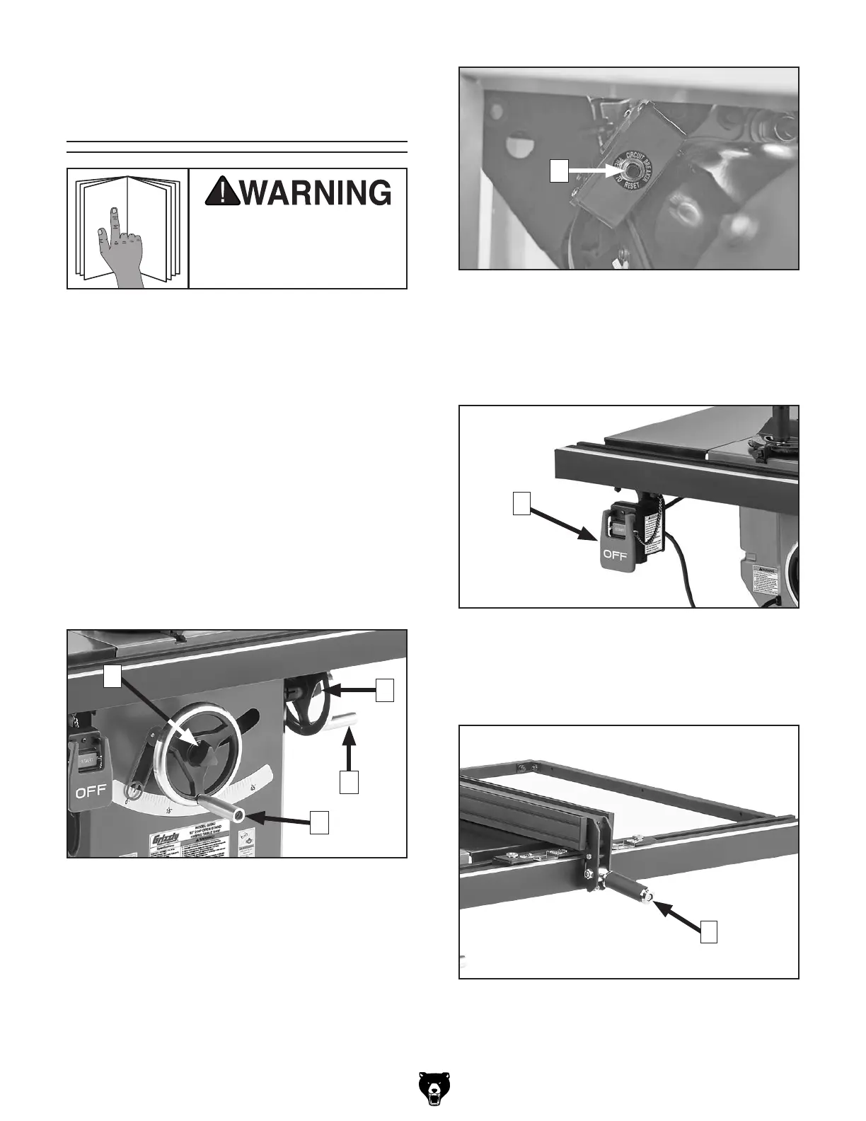
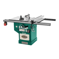
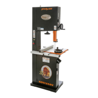
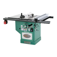
Figure 1. Blade adjustment handwheels and
locks.
Controls &
Components
Refer to the following figures and descriptions to
become familiar with the basic controls and com-
ponents of this machine. Understanding these
items and how they work will help you understand
the rest of the manual and minimize your risk of
injury when operating this machine.
A. Handwheel Locks: Lock blade height
and angle when tightened (one on each
handwheel).
B.
Blade Tilt Handwheel: Adjusts angle of
blade tilt from 0°–45°.
C. Blade Height Handwheel: Adjusts blade
height from 0"–3
1
⁄4".
E. START/STOP Switch: Starts and stops
motor. Switch can be disabled for safety by
inserting disabling pin or padlock (not includ-
ed) through START switch.
E
F. Fence Lock Handle: Locks fence when
pushed down, and unlocks fence when pulled
up.
C
B
A
A
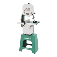
D. Reset Button: Resets machine after thermal
overload protection has tripped. To reset,
wait a few minutes for motor to cool, then
press reset button. If button does not stay
depressed, allow motor to cool longer, then
try again.
D
Figure 2. Location of Reset button.
Figure 3. Location of START/STOP switch.
F
Figure 4. Fence lock handle.