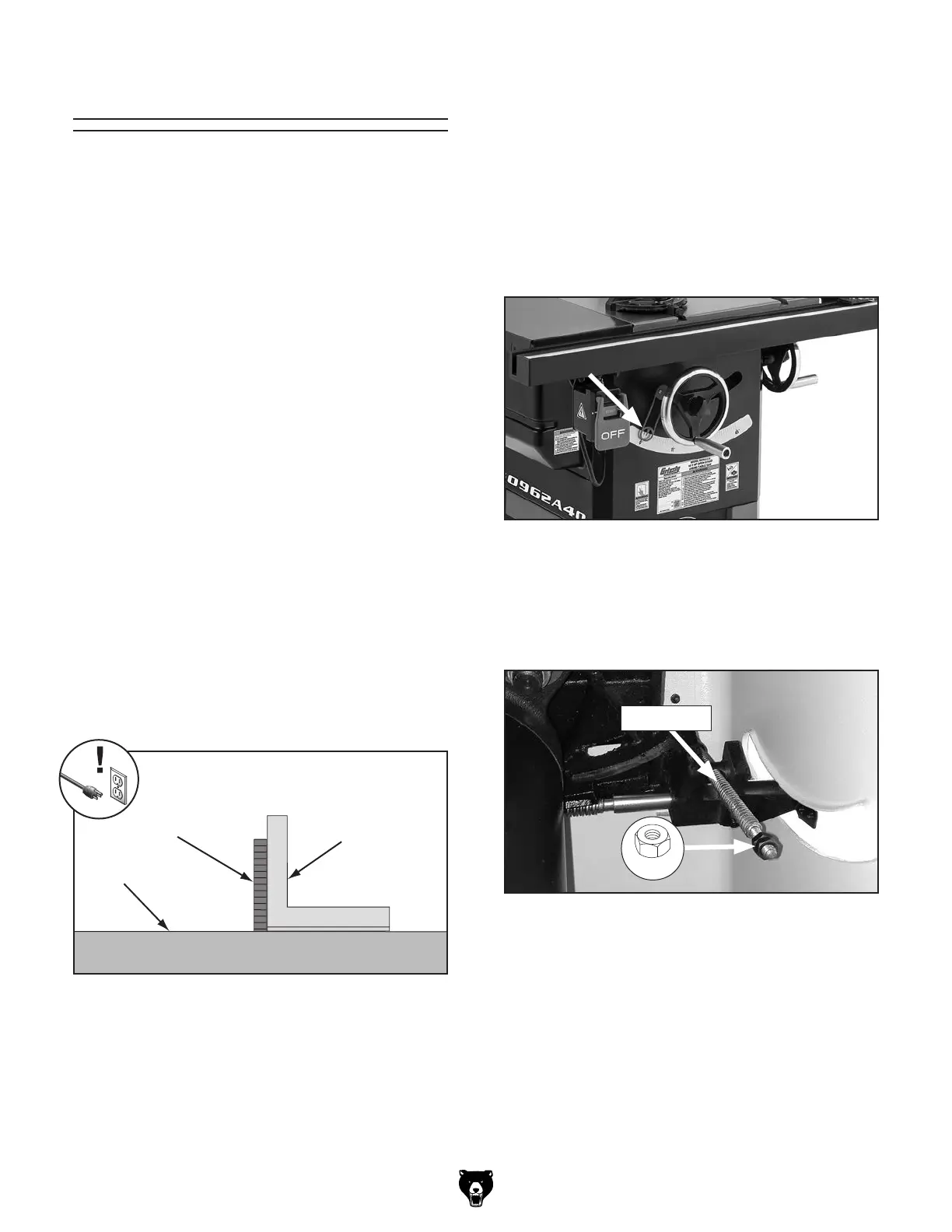
Figure 111. Checking blade at 90°.
Table
90° Square
Blade
Figure 112. Tilt indicator arrow location.
Figure 113. Location of 90° stop nuts.
Model G0962A40 (Mfd. Since 07/22)
-67-
The blade tilt settings for this saw have been set at
the factory and should not require adjustment dur-
ing assembly. However, after prolonged use, or if
the saw does not cut accurate bevels, the settings
should be checked and adjusted accordingly.
Note: The tilt scale reads "0" when the blade is
90° to the table.
Tools Needed Qty
90° Square ........................................................ 1
45° Square
........................................................ 1
Hex Wrenches 3, 4mm
................................1 Ea.
Open-End Wrench 13mm
.................................. 1
Phillips Head Screwdriver #2
............................ 1
Setting 90° Stop
1. DISCONNECT MACHINE FROM POWER!
2.
Raise blade as high as it will go, then tilt it
toward 90° until it stops and cannot be tilted
any more.
3.
Place a 90° square against table and blade
so it contacts blade evenly from bottom to
top, as shown in Figure 111. Make sure a
blade tooth does not obstruct placement of
square.
— If blade is 90° to table, then no adjust-
ments are necessary. Make sure tilt indi-
cator arrow shown in Figure 112 points
to 0° mark on scale. Adjust position by
loosening Phillips head screws, moving
indicator with your fingers, then tightening
screws.
— If blade is not 90° to table, you will need to
adjust 90° stop nuts. Proceed to Step 4.
4.
Remove motor cover.
5. Loosen (2) M8-1.25 hex nuts on leadscrew
(see Figure 113).
Leadscrew
x 2
Blade Tilt Calibration


 To Next Page