L
Laura ClarkeAug 18, 2025
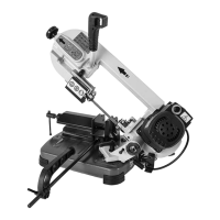
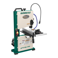
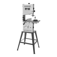
How to fix a Grizzly Saw blade that tracks incorrectly?
- MMark FletcherAug 18, 2025
If the blade on your Grizzly Saw is tracking incorrectly or coming off the wheels, it could be due to: * A feed rate that is too fast or the wrong TPI. * Blade tension or tracking needing adjustment. * Blade guides needing adjustment. * The blade being bell-mouthed. To address this, reduce the feed rate or decrease the blade TPI, adjust the blade tracking and tension, adjust the blade guides, or replace the blade.